
A glass composite insulator and its manufacturing method

A technology for composite insulators and manufacturing methods, applied in the direction of insulators, supporting insulators, suspension/strain insulators, etc., can solve the problems of large dispersion of mechanical strength, step-by-step molding, and poor appearance quality, so as to prevent deformation and improve electric resistance. Performance, beautiful appearance effect

Active Publication Date: 2017-08-25
南京电气绝缘子有限公司
View PDF11 Cites 0 Cited by
  • Summary
  • Abstract
  • Description
  • Claims
  • Application Information

AI Technical Summary

Problems solved by technology

This kind of process will make the glued fittings, glass parts and cement adhesives need to withstand the influence of high temperature of the mold, which will easily cause the dispersion of mechanical strength to increase; although the product has the characteristics of zero-value self-explosion of glass insulators, due to After forming and positioning of the fittings, the silica gel wraps and bonds the fittings at both ends at the same time, and the insulator cannot fall off or be visually identified after self-explosion
The molding process is prone to defects such as rubber nest gas, glass parts crushed, and multi-stage molding, many interfaces, and poor appearance quality

Method used


Image

  • A glass composite insulator and its manufacturing method

Examples


Embodiment Construction

[0020] The present invention will be further described below in conjunction with the accompanying drawings. The following examples are only used to illustrate the technical solution of the present invention more clearly, but not to limit the protection scope of the present invention.

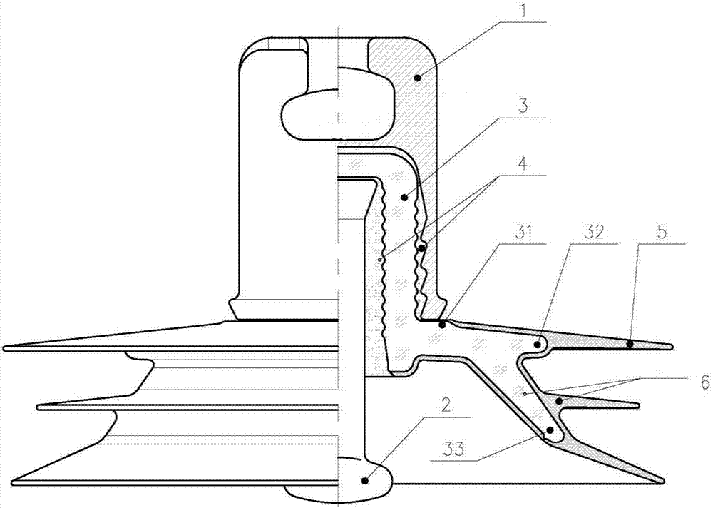
[0021] Such as figure 1 As shown, a glass composite insulator is characterized in that it mainly includes an iron cap 1, a glass part 3, a silicone rubber umbrella cover 5, and a steel foot 2, and the glass part 3 and the silicone rubber umbrella cover 5 are integrally connected to form an insulating part 6 , the glass piece is provided with at least two skeleton flutes along the direction of the silicone rubber shed, the flute skeletons are the first flute skeleton 32 and the second flute skeleton 33, the iron cap 1 and the steel foot 2 pass through The cement glue 4 is glued together with the insulating part 6, and the root of the glass part 3 is provided with a protrusion 31 and thickened by...


PUM

PropertyMeasurementUnit
thicknessaaaaaaaaaa

Abstract

A manufacturing method of a glass composite insulator includes the following steps: forming a glass part with a skeleton umbrella structure; covering and wrapping a silicone rubber umbrella cover on the glass part, adopting a combined mold integral injection method, using a combined mold, and silicone rubber umbrella cover (multiple sheds) The overall molding is beautiful in appearance, high in efficiency, reduces the interface, and improves the electrical performance of the product; adopts a multi-point symmetrical adjustable glue injection process and cooperates with the mold cavity pressure control scheme during the molding process to balance the force of each point of the glass part and prevent the glass part from being damaged. Squeeze and crush; the mold cavity is vacuumed as a whole to reduce the generation of rubber bubbles; the iron cap and steel cap are glued to the insulating parts by cement adhesive, which avoids the influence of high temperature of the mold on the performance of the cement adhesive, and greatly reduces the dispersion of mechanical properties of the product. The cement adhesive is not covered by silicone rubber, and the product completely inherits the zero-value self-explosion characteristics of the glass insulator; and avoids the influence of the straightness of the center of the cap leg produced by the cement glue fitting on the shape of the umbrella cover.

Description

technical field [0001] The invention relates to a glass composite insulator and a manufacturing method thereof. Background technique [0002] The glass composite insulator is a new type of insulator with a layer of silicone rubber attached to the glass surface of the glass insulator and a rubber shed. Theoretically, this type of insulator combines some features of glass insulators and composite insulators. With certain performance advantages, it has been gradually accepted and used by the power market in recent years. [0003] The commonly used glass composite insulators are generally glued first and then formed. First, the fittings at both ends (iron caps, steel feet) are glued together with cement and glass parts, and then molded part of the shed and bonded with silicon. The molding of the silicone rubber umbrella skirt is completed by methods such as rubber umbrella skirt and smearing room temperature vulcanized silicone rubber. This kind of process will make the glued...

Claims


Application Information

Patent Timeline
Patent Type & Authority Patents(China)
IPC IPC(8): H01B17/02H01B17/14H01B17/38H01B19/00
Inventor 石玉秉张善钢崔超群赵一平
Owner 南京电气绝缘子有限公司
Learn More