Method for realizing cell switching of multi-electrolyte battery by using conduction of electrolytes

A battery cell and electrolyte technology, applied in the field of multi-electrolyte battery cell switch, can solve the problems of energy loss, failure to turn off the battery, limit the selection range of battery cathode and anode materials, etc., to achieve double protection and improve safety Effect

Inactive Publication Date: 2016-02-24
GUANGZHOU DAODONG NEW ENERGY CO LTD
View PDF2 Cites 5 Cited by
  • Summary
  • Abstract
  • Description
  • Claims
  • Application Information

AI Technical Summary

Problems solved by technology

However, there are two major technical problems in the battery structure of a single electrolyte: (1) Since the cathode and anode of the battery are directly inserted into the electrolyte, the cathode and anode materials of the battery must be compatible with the single electrolyte at the same time. When developing a new battery, It greatly limits the range of selection of battery cathode and anode materials; (2) the composition and concentration of a single electrolyte are difficult to ensure that the electrochemical reactions of the cathode and anode reach the best state (maximum activity) at the same time during battery use, which is not conducive to the performance of the battery. Its maximum electrochemical performance
[0004] In addition, the existing batteries all control the switch of the battery through an external circuit, and the battery cell itself does not have the function of controlling the switch of the battery. Batteries, resulting in accidents, the safety of this type of battery cannot meet the needs of technological development
At the same time, the self-discharge of existing batteries leads to a loss of energy

Method used


Image

  • Method for realizing cell switching of multi-electrolyte battery by using conduction of electrolytes

Examples


Embodiment 1

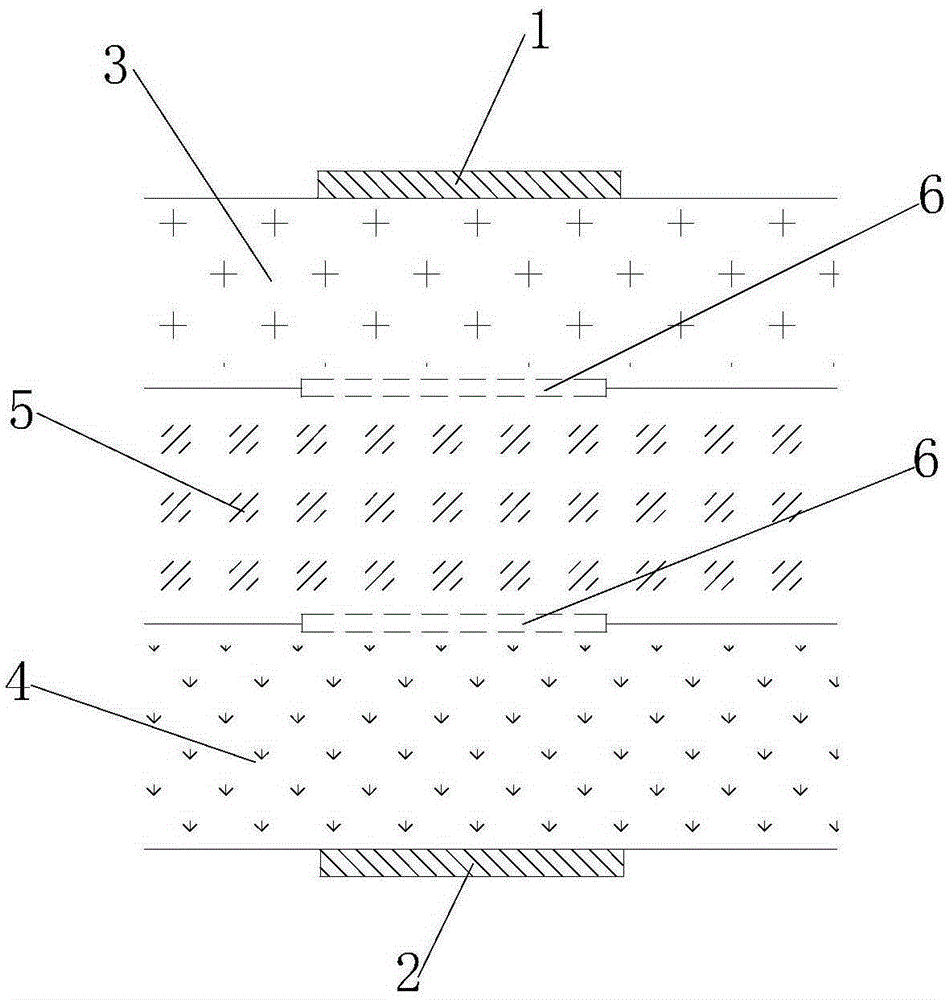
[0023] Such as figure 1 As shown, a multi-electrolyte battery of the present embodiment, the multi-electrolyte battery includes an anode plate 1, a cathode plate 2, and an electrolyte, and the electrolyte includes an anolyte 3, a catholyte 4, and a bridge electrolyte 5. The anolyte 3 is in contact with the anode plate 1, the catholyte 4 is in contact with the cathode plate 2, and the bridge electrolyte 5 is placed between the anolyte 3 and the catholyte 4 to form an ion conduction channel, And separated by ion exchange membrane 6 respectively.

[0024] The anode plate 1 and the cathode plate 2 of the present embodiment are in contact with the anolyte 3 and the catholyte 4 respectively and undergo an electrochemical reaction, and the bridge electrolyte 5 passes through the ion exchange membrane 6 and the anolyte 3 and the catholyte respectively. 4 Selective conduction of ions, the battery cathode and anode materials do not need to be compatible with an electrolyte at the same ...

Embodiment 2

[0027] This embodiment provides a method for realizing the above-mentioned multi-electrolyte battery cell switch by using the conduction of the electrolyte, including the following steps: draining any one of the electrolytes, so that the electrolytes are in non-conduction state, the ion conduction channel is cut off, and the battery stops working. As mentioned above, the bridge electrolyte 5 selectively conducts ions through the ion exchange membrane 6, the anolyte 3, and the catholyte 4 to form ion conduction channels, so that the anode plate 1 and the cathode plate 2 are connected to the anode plate 2 respectively. When the electrolyte 3 and the catholyte 4 are in contact and electrochemical reaction occurs, the battery is in a working state. When the electrolyte is in a non-conductive state through control, and then the ion conduction channel is cut off, it is convenient to realize the When the battery is turned off, the battery cell itself has the function of a battery swi...

Embodiment 3

[0032] This embodiment provides a method for realizing the above-mentioned multi-electrolyte battery cell switch by using the conduction of the electrolyte, which includes the following steps: replacing any one of the electrolytes with an insulating liquid, so that the electrolytes are in a non-conductive state. In the conduction state, the ion conduction channel is cut off, and the battery stops working.

[0033] As a preferred solution, if the bridge electrolyte 5 is replaced with an insulating liquid, the ion conduction channel will be cut off, and the battery will stop working.

[0034] As another preferred solution, if the catholyte 4 is replaced with an insulating liquid, the ion conduction channel will be cut off, and the battery will stop working.

[0035] As another preferred solution, if the anolyte 3 is replaced with an insulating liquid, the ion conduction channel will be cut off, and the battery will stop working.

[0036] Wherein, the insulating liquid is a fluo...


PUM


Abstract

The invention relates to the technical field of batteries, and concretely relates to a method for realizing cell switching of a multi-electrolyte battery by using conduction of electrolytes. The multi-electrolyte battery comprises an anode plate, a cathode plate and electrolytes, the electrolytes comprises an anode electrolyte, a cathode electrode and a bridge electrolyte, the anode electrolyte is in contact with the anode plate, the cathode electrode is in contact with the cathode plate, the bridge electrolyte is placed between the anode electrolyte and the cathode electrolyte to form an ion conduction channel, and the bridge electrolyte, the anode electrolyte and the cathode electrolyte are respectively separated by ion exchange films. The electrolytes are controlled to be in a non-conduction state to cut out the ion conduction channel in order to conveniently realize off of the battery, so the cell of the battery also has a battery switching function, thereby dual protection of a circuit is realized, and the safety of the battery is greatly improved; and the self-discharge of the battery can be reduced to a lowest limit when the electrolytes are in a non-conduction state.

Description

technical field [0001] The invention relates to the field of battery technology, in particular to a method for realizing switching of cells of a multi-electrolyte battery by utilizing the conduction of electrolyte. Background technique [0002] Battery (Battery) refers to a part of the space of a cup, tank or other container or composite container that contains an electrolyte solution and a metal electrode to generate current. It can convert chemical energy into electrical energy. Using a battery as an energy source, a stable voltage can be obtained. , stable current, stable power supply for a long time, current that is little affected by the outside world, and the battery structure is simple, easy to carry, easy to charge and discharge, not affected by the external climate and temperature, stable and reliable performance, in modern social life play a significant role in all aspects. [0003] At present, commercialized batteries on the market, such as lithium-ion batteries,...

Claims


Application Information

Patent Timeline
Patent Type & Authority Applications(China)
IPC IPC(8): H01M10/42
CPCH01M10/4235H01M10/42Y02E60/10
Inventor 刘富德郑大伟
Owner GUANGZHOU DAODONG NEW ENERGY CO LTD
Why Eureka
Try Eureka