A high-precision antenna for a full navigation system

A navigation system and high-precision technology, applied in the field of satellite navigation antennas, can solve the problems of poor pattern consistency, lack of L/S simultaneous coverage, and poor pattern symmetry, achieving improved symmetry and excellent low-elevation characteristics. , the effect of free from debugging

Active Publication Date: 2018-04-10
BEIJING RES INST OF TELEMETRY +1
View PDF4 Cites 2 Cited by
  • Summary
  • Abstract
  • Description
  • Claims
  • Application Information

AI Technical Summary

Problems solved by technology

[0004] In addition, in recent years, some people have applied the planar helical antenna to the field of high-precision navigation antennas. Although the planar helical antenna has a wide standing wave bandwidth, the symmetry of its pattern is poor, and with the change of frequency, the symmetry of the pattern Consistency is also poor
Although the high-precision antennas of the foreign mainstream products GNSS750 and AR25 series have been widely used in the field of L-band navigation, they do not have the ability of L / S simultaneous coverage

Method used


Image

  • A high-precision antenna for a full navigation system
  • A high-precision antenna for a full navigation system
  • A high-precision antenna for a full navigation system

Examples


Embodiment Construction

[0019] The working principle and working process of the present invention will be further explained and illustrated below in conjunction with the accompanying drawings.

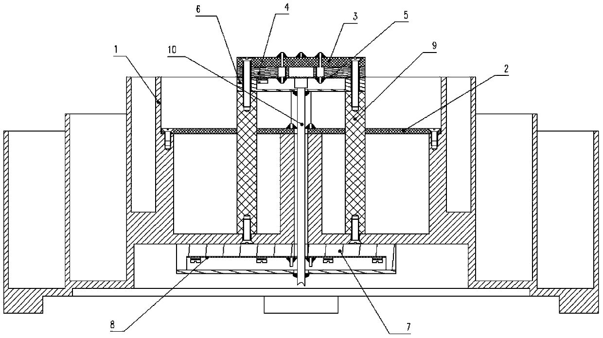
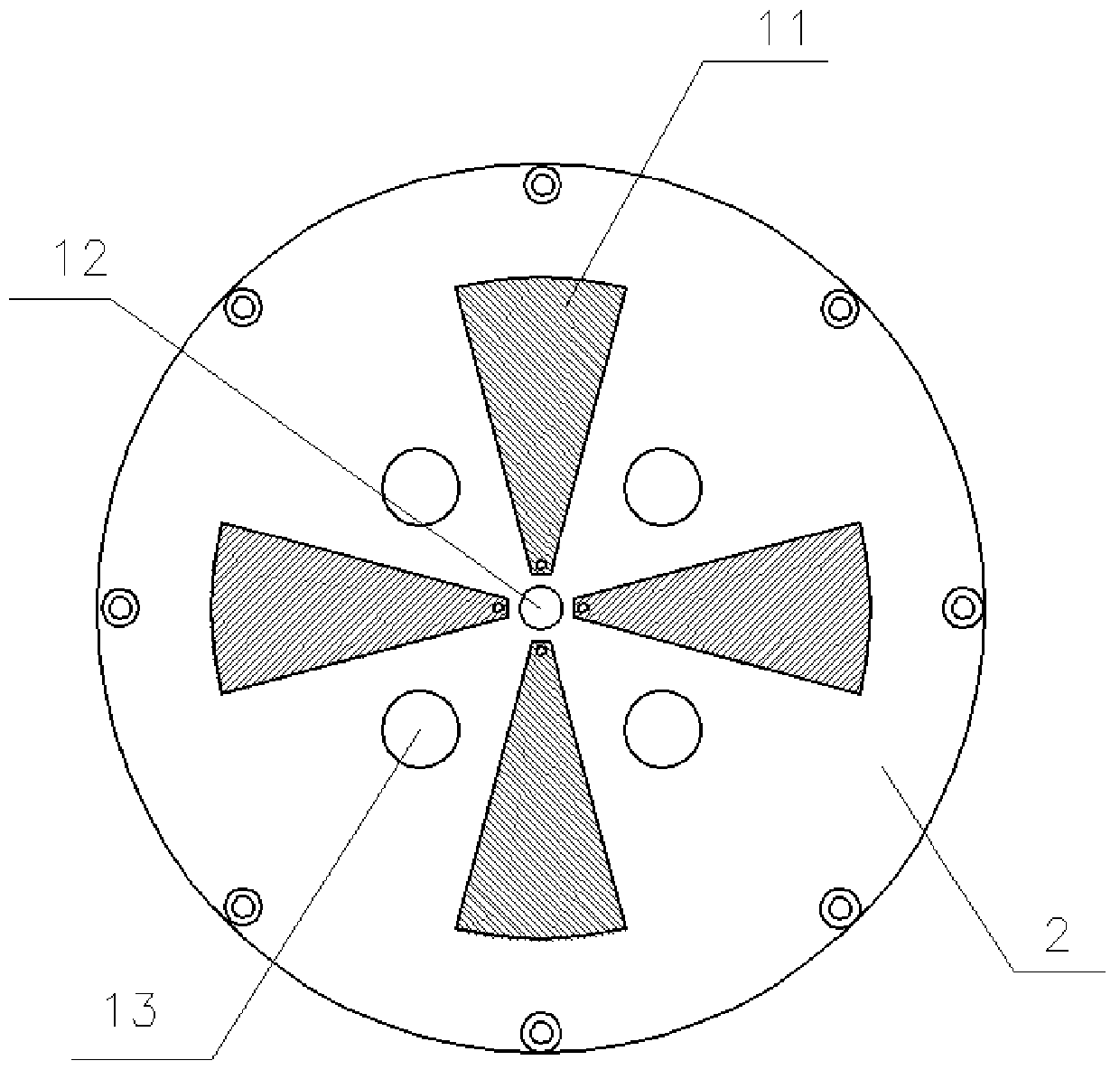
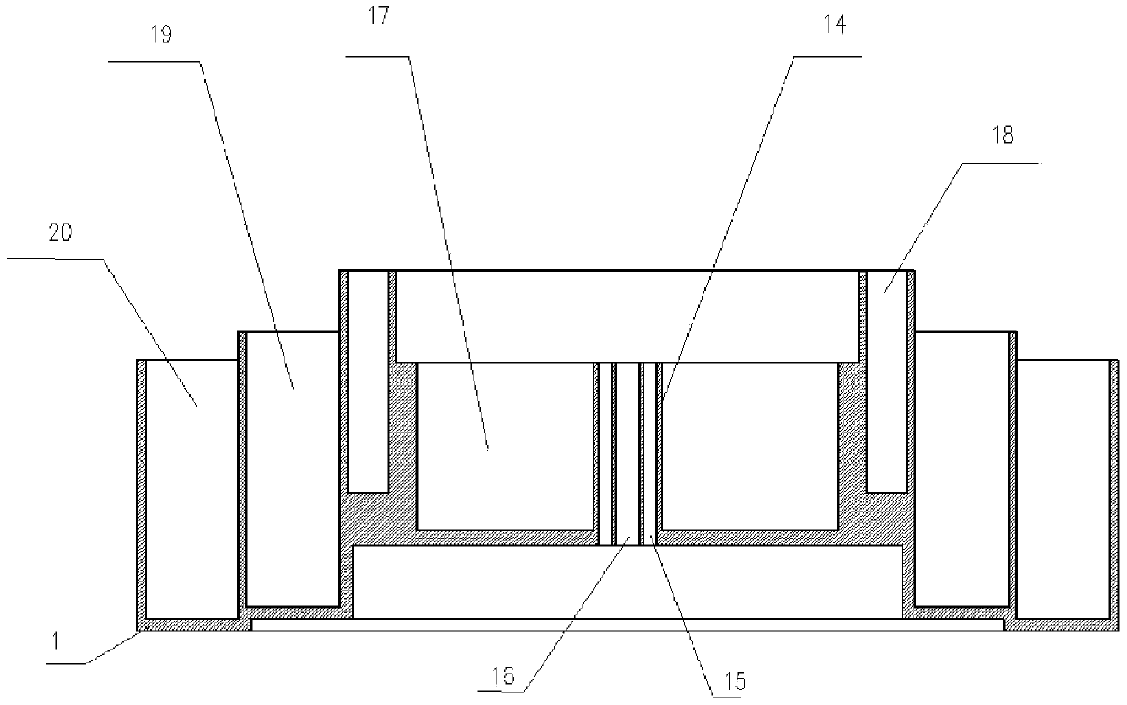
[0020] like figure 1 As shown, a high-precision antenna for a full navigation system includes: a three-dimensional choke coil 1, a microstrip petal vibrator 2, a microstrip printed board 3, a microstrip floor 4, an S bridge printed board 5, and an S bridge box 6 , L bridge box 7, L bridge printed board 8, support bracket 9, S feeder 10; microstrip petal oscillator 2 is fixedly installed in the three-dimensional choke coil 1; four support brackets 9 are fixedly installed in the three-dimensional choke coil The central position of the circle 1; the microstrip printed board 3, the microstrip floor 4, the S bridge printed board 5 and the S bridge box 6 are fixed on the support bracket 9 in sequence; the S feeder 10 passes through the L bridge printed circuit in turn Board 8, L bridge box 7, microstrip petal vibr...


PUM


Abstract

The invention discloses a high-accuracy antenna for an omnibearing navigation system. The high-accuracy antenna comprises a three-dimensional choking coil, a petal microstrip oscillator, a microstrip printed board, a microstrip floor, an S bridge printed board, an S bridge box, an L bridge box, an L bridge printed board, four support brackets and an S feed line, wherein the petal microstrip oscillator is fixedly arranged in the three-dimensional choking coil; the four support brackets are fixedly arranged at the center position of the three-dimensional choking coil; the microstrip printed board, the microstrip floor, the S bridge printed board and the S bridge box are sequentially fixed on the support frames; the S feed line sequentially passes through the L bridge printed board, the L bridge box, the petal microstrip oscillator and the S bridge box and is connected with the S bridge printed board; and the L bridge printed board and the L bridge box are sequentially fixed at the bottom of the three-dimensional choking coil. According to the high-accuracy antenna for the omnibearing navigation system, the broadband characteristic, the high-phase center stability characteristic, the high multipath suppression characteristic and the adjustment-free characteristic can be achieved.

Description

technical field [0001] The invention relates to a satellite navigation antenna, in particular to a high phase center stability antenna covering all navigation systems. Background technique [0002] With the continuous development of the US GPS system, the Russian GLONASS system, the Galileo system, and my country's "Beidou-2" satellite navigation and positioning system, satellite navigation precision measurement technology has been widely used in many fields of economic construction and scientific research, especially in geodesy. And related disciplines, including marine geodesy, resource exploration, engineering survey and engineering deformation monitoring, etc. The high-precision antenna of the whole navigation system is an important part of the monitoring receiver, and its performance is directly related to the measurement accuracy of the receiver. Among them, the phase center change and multipath effect of the antenna are significant error sources in the receiver system,...

Claims


Application Information

Patent Timeline
Patent Type & Authority Patents(China)
IPC IPC(8): H01Q1/36H01Q1/38H01Q7/00H01Q1/50
CPCH01Q1/36H01Q1/38H01Q1/50H01Q7/00
Inventor 刘庆辉郭丽陈剑
Owner BEIJING RES INST OF TELEMETRY
Why Eureka
Try Eureka