Burr-free bidirectional detachable luminous punch with sterilization function

A burr-free, punch-free technology, used in optics, light guides, optical components, etc., can solve the problems of increasing the burden on enterprises, increasing the cost of use, and small scope of application, to ensure firmness and reliability, easy to use and operate, and convenient. The effect of changing the blade

Inactive Publication Date: 2016-03-02
殷霄
View PDF6 Cites 0 Cited by
  • Summary
  • Abstract
  • Description
  • Claims
  • Application Information

AI Technical Summary

Problems solved by technology

[0002] The punch seat and the blade of the current punch are integrally formed. After the blade is used for a long time, it is gradually consumed due to wear and tear. Finally, the blade cannot be used because it is damaged and scrapped. Since the blade and the punch seat cannot be separated, the whole punch is also If it is scrapped, the punch needs to be replaced again, which greatly increases the cost of use and increases the burden on the enterprise
At the same time, the current punch stamping products are easy to form burrs on the fracture surface of the product, which reduces the quality of the product and cannot meet the requirements of some product finishing.
In addition, most of the current punches are one-way punches. Generally, only one blade is fixed on the punch seat, which can only be produced on one side. The scope of application is small and the cost of use is high.
At the same time, at present, bacteria are quite easy to remain on the knives, causing the hygienic quality of the knives to be considered, which will also have an adverse effect on the production and processing of the aseptic workshop, and the current knives cannot emit light, so when the light is dark, the operator cannot It is better to use knives, and there are certain safety hazards, which have a greater impact on the operation

Method used


Image

  • Burr-free bidirectional detachable luminous punch with sterilization function

Examples


Embodiment Construction

[0013] The present invention will be further described below in conjunction with the accompanying drawings.

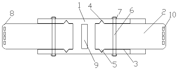
[0014] Such as figure 1 As shown, a burr-free two-way detachable sterilizing luminescent punch includes a punch seat 1, a blade 2, a screw 6 and a nut 7, and an opening 3 is recessed inward at both ends of the punch seat 1, and each A blade 2 is arranged in each opening 3, and the screw rod 6 passes through the rear end of the corresponding blade 2 and the part of the punch seat 1 on both sides of the opening 3, and the part of the screw rod 6 passing through the punch seat 1 is locked by a nut 7 For fixing, slots 4 are respectively arranged on both sides of each opening 3 , and the two pairs of slots 4 are located between two screw rods 6 . Protruding undercuts 5 are respectively provided on both sides of the rear end of the blade 2, and the undercuts 5 on both sides are matched with the slots 4 on the corresponding side to be clamped, and the two sides of the proces...


PUM


Abstract

The invention discloses a burr-free bidirectional detachable luminous punch with a sterilization function. The two ends of a punch base are each provided with an opening in an inwards concave mode. Each opening is provided with one blade inside, and screws penetrate through the rear ends of the corresponding blades and the parts, located on the two sides of the openings, of the punch base. Moreover, the parts, penetrating out of the punch base, of the screws are locked and fixed by nuts. The two sides of each opening are each provided with a slot. The two sides of the rear end of each blade are each provided with a convex inversed buckle, and the inversed buckles on the two sides are tightly clamped to the slots in the corresponding sides in a matched mode. The two sides of the machining end of each blade are arranged to be fillets, a light source is arranged on the punch base and generates ultraviolet light, and a plurality of light guide pieces are arranged on the blades, located on the edges of the cutting edges of the blades and perpendicular to the cutting edges. The light guide pieces absorb light emitted by the light source and guide the light to the cutting edges.

Description

technical field [0001] The invention relates to a punch, in particular to a burr-free bidirectional detachable sterilizing light-emitting punch. Background technique [0002] The punch seat and the blade of the current punch are integrally formed. After the blade is used for a long time, it is gradually consumed due to wear and tear. Finally, the blade cannot be used because it is damaged and scrapped. Since the blade and the punch seat cannot be separated, the whole punch is also If it is scrapped, the punch needs to be replaced again, which greatly increases the cost of use and increases the burden on the enterprise. At the same time, the current punch stamping products are easy to form burrs on the fracture surface of the product, which reduces the quality of the product and cannot meet the requirements of some product finishing. In addition, most of the current punches are one-way punches, and generally only one blade is fixed on the punch seat, which can only be produc...

Claims


Application Information

Patent Timeline
Patent Type & Authority Applications(China)
IPC IPC(8): B21D28/14A61L2/10F21V33/00F21V8/00
Inventor 殷霄
Owner 殷霄
Why Eureka
Try Eureka