
Control method for purging gun for continuous casting billet defect smelting removal equipment

A technology of purge gun and continuous casting slab, which is applied in the control field of purge gun for continuous casting slab defect melting equipment. The effect of sweeping quality, reducing labor intensity and high degree of mechanization

Active Publication Date: 2016-03-02
MCC BAOSTEEL TECH SERVICE
View PDF7 Cites 2 Cited by
  • Summary
  • Abstract
  • Description
  • Claims
  • Application Information

AI Technical Summary

Problems solved by technology

When purging, if the angle between the purge gun and the steel plate is not good, it will directly lead to the decline of the purging quality
During manual cleaning, the operator mainly relies on experience to adjust the angle between the purge gun and the steel plate. At the same time, the purge gun is relatively heavy, and it is laborious for workers to hold the purge gun.
It can be seen that the whole operation process mainly relies on manual operation, the degree of mechanization is low, the labor intensity of operators is relatively high, and the quality of blowing is low

Method used


Image

  • Control method for purging gun for continuous casting billet defect smelting removal equipment
  • Control method for purging gun for continuous casting billet defect smelting removal equipment
  • Control method for purging gun for continuous casting billet defect smelting removal equipment

Examples


Embodiment Construction

[0034] The implementation of the present invention will be illustrated by specific specific examples below, and those skilled in the art can easily understand other advantages and effects of the present invention from the contents disclosed in this specification.

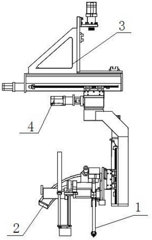
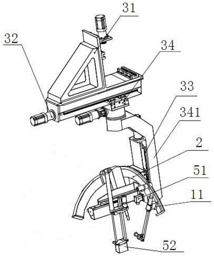
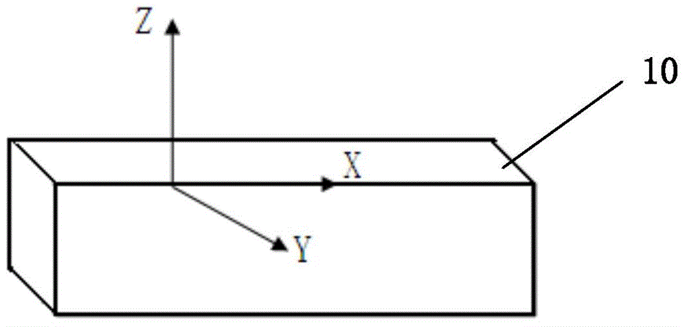
[0035] see Figure 1 to Figure 3 . It should be noted that the structures, proportions, sizes, etc. shown in the drawings attached to this specification are only used to match the content disclosed in the specification, for those who are familiar with this technology to understand and read, and are not used to limit the implementation of the present invention. Limiting conditions, so there is no technical substantive meaning, any modification of structure, change of proportional relationship or adjustment of size, without affecting the effect and purpose of the present invention, should still fall within the scope of the present invention. within the scope covered by the disclosed technical content. At the same ti...


PUM


Abstract

The invention provides a control method for a purging gun for continuous casting billet defect smelting removal equipment. The purging gun is arranged on a purging swinging angle structure. The purging swinging angle structure is connected with a three-axis mechanical arm. A rotary servo motor is arranged on the three-axis mechanical arm. When steel plate surface X-direction defects are removed, a 15-degree included angle is formed between a gun head of the purging gun and the steel plate Z-direction axis, and a 15-degree included angle is formed between the gun head and the steel plate Y-direction axis. A 15-degree included angle is formed between the gun head of the purging gun and the steel plate Y-direction axis, and a 15-degree included angle is formed between the gun head and the steel plate Z-direction axis. When steel plate side X-direction defects are removed, a 15-degree included angle is formed between the gun head of the purging gun and the steel plate Y-direction axis, and a 15-degree included angle is formed between the gun head and the steel plate Z-direction axis. When steel plate corner X-direction defects are removed, a 15-degree included angle is formed between the gun head of the purging gun and the steel plate corner X-direction axis. When steel plate corner Y-direction defects are removed, a 15-degree included angle is formed between the gun head of the purging gun and the steel plate corner Y-direction axis. According to the control method, the labor intensity of operators can be relieved and purging quality can be improved.

Description

technical field [0001] The invention relates to a purge gun for continuous casting slab defect melting equipment, in particular to a control method for the continuous casting slab defect melting equipment for the purging gun. Background technique [0002] The defects of continuous casting slabs are mainly divided into surface defects, internal defects and shape defects. The melting of defects in continuous casting slabs has always been a difficult problem for steel mills. At present, the defects of continuous casting slabs are mainly cleaned manually, and the cleaning process mainly relies on visual observation to ensure the surface quality of the steel plate to the maximum extent. [0003] Manual cleaning is a highly technical job, operators must undergo professional training, and special operating certificates are required for specific positions. The cleaning quality of the continuous casting slab is greatly affected by the skill level of the personnel. In order to ensure...

Claims


Application Information

Patent Timeline
IPC IPC(8): B22D11/12
Inventor 陆永刚董朔范黄山柯友金第少华
Owner MCC BAOSTEEL TECH SERVICE
Features
  • Generate Ideas
  • Intellectual Property
  • Life Sciences
  • Materials
  • Tech Scout
  • Unparalleled Data Quality
  • Higher Quality Content
  • 60% Fewer Hallucinations
Learn More