Backfill type stir friction spot welding device

A friction stir and spot welding device technology, applied in welding equipment, non-electric welding equipment, metal processing equipment, etc., can solve problems such as large moment of inertia, vibration, and short service life

Active Publication Date: 2016-03-02
苏州市哈工万洲自动化有限公司
View PDF6 Cites 10 Cited by
  • Summary
  • Abstract
  • Description
  • Claims
  • Application Information

AI Technical Summary

Problems solved by technology

The existing backfill friction stir spot welding device has disadvantages such as complex power transmission system, poor stability, easy deformation of the stirring needle and sleeve, poor spot welding effect, short service life, and large overall volume of the device.
[0004] In November 2013, the State Intellectual Property Office published an invention patent application titled: A backfill friction stir welding method and its device, application number: 201310347507.X, although the device realizes backfill friction stir spot welding function, but it still has the following defects: 1. The stirring needle drives the sleeve to rotate through the spline pair, and the inner layer drives the outer layer to rotate. The torque is large, the power requirement is high, and the energy efficiency is low; 2. The transm

Method used


Image

  • Backfill type stir friction spot welding device

Examples


Embodiment Construction

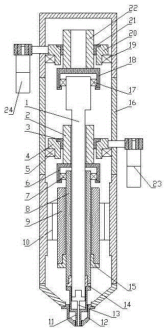
[0015] Such as figure 1 The shown backfill type friction stir spot welding device comprises an outer shell 16 and a stirring head made up of a stirring needle 13, a tubular sleeve 11 and a jacket 12, and the jacket 12 is fixed on the lower end of the outer shell 16 for compressing the Welding workpiece, sleeve 11 can freely rotate and slide up and down in the jacket 12, stirring pin 13 can slide up and down in the sleeve 11, the contact surface between sleeve 11 and stirring needle 13 and the sleeve and The contact surfaces of the jacket are all mirror surfaces, a hollow shaft motor 10 is arranged in the housing, a hollow sleeve shaft 8 is arranged in the hollow main shaft 9 of the hollow shaft motor 10, a stirring needle shaft 1 is arranged in the sleeve shaft 8, and a stirring needle shaft 1 is arranged in the sleeve shaft 8. Both the shaft 8 and the stirring pin shaft 1 are spline shafts, the hollow main shaft 9 is provided with a sleeve spline sleeve 15 matching with the s...


PUM


Abstract

The invention discloses a backfill type stir friction spot welding device, and relates to the technical field of stir friction welding. A jacket is fixed at the lower end part of an outer shell; an arm cover is arranged in the jacket; a stirring needle is arranged in the arm cover; a hollow shaft motor is provided; a hollow arm cover shaft is arranged in the hollow shaft motor; a stirring needle shaft is arranged in the arm cover shaft; the arm cover shaft is connected with the arm cover; the stirring needle shaft is connected with the stirring needle; a first ball screw with a screw rod as a hollow screw rod is arranged above the arm cover shaft; the stirring needle shaft is inserted in the screw rod of the first ball screw; a first bearing frame is arranged at the lower end of the screw rod of the first ball screw; the upper end part of the arm cover shaft is mounted on the first bearing frame; a second ball screw is arranged above the stirring needle shaft; a second bearing frame is arranged at the lower end of a screw rod of the second ball screw; the upper end part of the stirring needle shaft is mounted on the second bearing frame; and a first power source and a second power source are respectively connected with nuts of two lead screws. The backfill type stir friction spot welding device has such advantages as simple structure, high system stability, high welding precision, good effect and long service life.

Description

technical field [0001] The invention relates to the technical field of friction stir welding, and in detail is a backfilling friction stir spot welding device with simple structure, high system stability, high welding precision, good effect and long service life. Background technique [0002] As the society pays more and more attention to energy conservation and environmental protection, lightweight has become the development direction of modern transportation industries such as automobiles and motor vehicles, as well as industrial manufacturing fields such as aerospace. This makes the application of lightweight and high-strength materials such as aluminum alloys and magnesium alloys more and more widely concerned, but at the same time it also puts forward higher requirements for the connection technology of these materials. Due to its light weight and high strength, aluminum alloy is widely used in various industries, especially the automobile and aviation industries. At p...

Claims


Application Information

Patent Timeline
IPC IPC(8): B23K20/12B23K20/26
CPCB23K20/12B23K20/26
Inventor 周利王瑞张锦标冯吉才
Owner 苏州市哈工万洲自动化有限公司
Why Eureka
Try Eureka