
Sediment removal system and method for preventing sediment accumulation at canal bed of canal and

A sedimentation and drainage technology, which is applied in water conservancy projects, river regulation, sea area engineering, etc., can solve problems such as increased project costs, hidden safety hazards, hydraulic machinery wear, etc., and achieves improved sand discharge efficiency, safety and sand discharge, The effect of low-cost sand removal

Active Publication Date: 2016-03-02
XIHUA UNIV
View PDF8 Cites 4 Cited by
  • Summary
  • Abstract
  • Description
  • Claims
  • Application Information

AI Technical Summary

Problems solved by technology

The diversion channel of the hydropower station is difficult to operate due to sedimentation, the service life of the reservoir is shortened due to sedimentation, and the hydraulic machinery is severely worn due to the sand carried by the water flow, resulting in a significant reduction in efficiency
[0003] At present, in order to achieve sand discharge, it is usually necessary to design a sand discharge channel at the bottom of the dike of the canal, and the sand discharge channel passing through the dike will undoubtedly affect the structural strength of the dike, bring certain safety hazards, or reduce the engineering cost of the canal. Therefore, how to discharge sand more safely and at low cost has become a technical problem to be solved urgently by those skilled in the art

Method used


Image

  • Sediment removal system and method for preventing sediment accumulation at canal bed of canal and
  • Sediment removal system and method for preventing sediment accumulation at canal bed of canal and

Examples


Embodiment Construction

[0025] For ease of understanding, the present invention will be further described below in conjunction with the accompanying drawings.

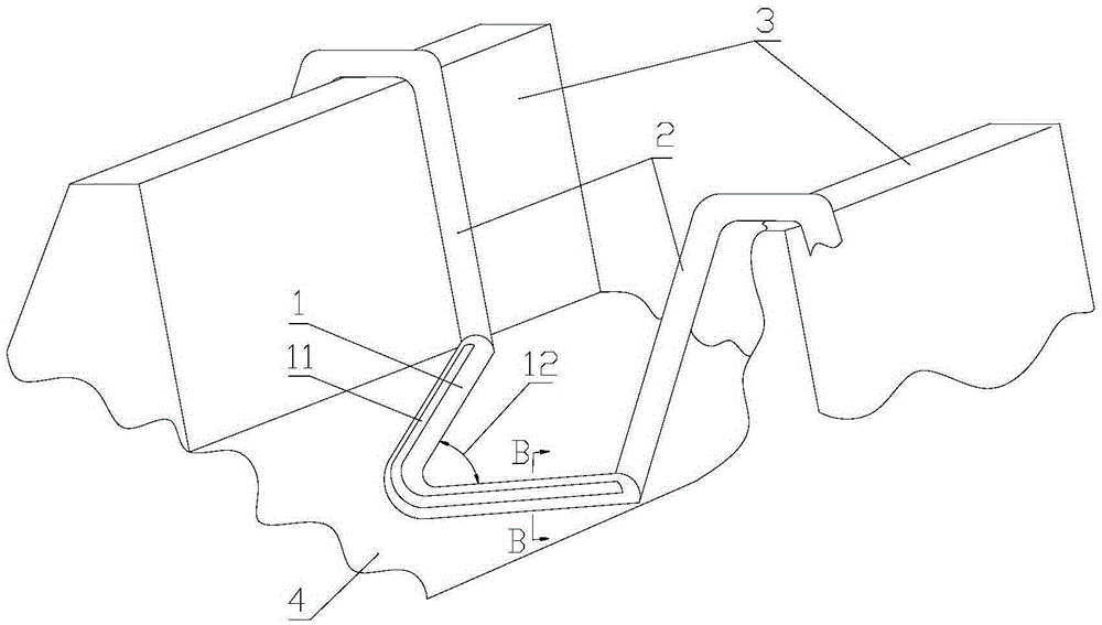
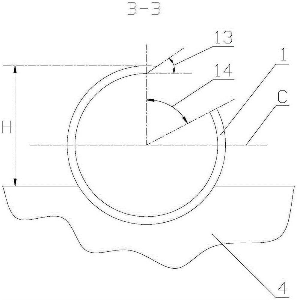
[0026] see figure 1 and figure 2 , figure 1 is a schematic diagram of a sand discharge system provided by the present invention, figure 2 yes figure 1 Middle B-B sectional view.

[0027] The sand discharge system provided by the present invention includes a vortex tube 1 and a siphon tube 2, wherein the vortex tube 1 is located at the bottom 4 of the water channel, and is used to form a spiral flow. The vortex tube 1 is V-shaped, and the V-shaped sharp corner points to the opposite direction of the water flow. The upstream side of the tube 1 is provided with an opening 11 extending along the axis of the tube, and the end of the vortex tube 1 is close to the bottom of the dike 3; Outside the canal.

[0028] The V-shaped included angle 12 of the vortex tube 1 may be 60°-120°. The diameter of the vortex tube 1 is generally 80 mm to 100 ...


PUM


Abstract

The invention provides a sediment removal system and a method for preventing sediment accumulation at a canal bed of a canal. The sediment removal system comprises a V-shaped vortex pipe and siphons, wherein the V-shaped vortex pipe is positioned at the canal bed of the canal, and is used to form spiral flows; a V-shaped sharp corner points to the direction opposite to the direction of a water flow; openings are formed in the water flow facing sides of the vortex pipe; the tail ends of the vortex pipe are close to the bottom of a canal bank of the canal; one end of one siphon is communicated with one tail end of the vortex pipe correspondingly; and the other ends of the siphons bypass the tops of the canal bank to extend to the outer sides of the canal. According to the sediment removal system and the method, the flow speeds of helical flows along the axial directions of the vortex pipe can be increased through the siphons, so that the sediment removal efficiency is improved, the sediment removal system is green and environmental-friendly; in addition, the siphons bypass the top of the canal bank to extend to the outer sides of the canal, so that the impact on the structural strength of the canal bank is avoided; moreover, the vortex pipe of the sediment removal system is V-shaped, so that the two helical flows flowing to the two tail ends of the vortex pipe respectively can be formed, the siphons can be arranged at the two tail ends of the vortex pipe, and the sediment removal efficiency is improved.

Description

technical field [0001] The invention relates to the technical field of sediment dredging at the bottom of a diversion channel of a hydropower station, in particular to a method and a sand discharge system for preventing sediment deposition at the bottom of a water channel. Background technique [0002] Sediment problems plague many water conservancy projects. The diversion channel of the hydropower station is difficult to operate due to sedimentation, the service life of the reservoir is shortened due to sedimentation, and the hydraulic machinery is severely worn due to the sand entrained by the water flow, resulting in a significant reduction in efficiency. [0003] At present, in order to achieve sand discharge, it is usually necessary to design a sand discharge channel at the bottom of the dike of the canal, and the sand discharge channel passing through the dike will undoubtedly affect the structural strength of the dike, bring certain safety hazards, or reduce the engin...

Claims


Application Information

Patent Timeline
Patent Type & Authority Applications(China)
IPC IPC(8): E02B3/02
CPCE02B3/023
Inventor 张聪刘小兵曾永忠
Owner XIHUA UNIV
Learn More