Water turbine

A water turbine and outlet technology, which is applied in the fields of hydropower, mechanical equipment, engine components, etc., can solve the problems of reduced unit output, inability to remove, and blocked nozzle debris, so as to increase annual power generation, avoid power generation losses, and improve the overall well-structured effect

Inactive Publication Date: 2016-03-02
黄国宏
View PDF1 Cites 11 Cited by
  • Summary
  • Abstract
  • Description
  • Claims
  • Application Information

AI Technical Summary

Problems solved by technology

[0002] At present, the impulse turbines used in hydropower production can only be used for high-head and low-flow hydropower resources, but cannot adapt to hydropower resources that generally exist in the form of low-head and large-flow
And, the deficiency that this impulse type water turbine exists is: serious collision phenomenon will be produced when the high-speed water flow injected around the circular spray needle of circular nozzle and its internal device is concentrated to its end center, and the water flow of injection nozzle The water flow pressure energy cannot be efficiently converted into water flow energy; when there is debris jamming in the nozzle, it cannot be removed; the water discharged from the inside of the runner water bucket rushes to the back of the water bucket in front of it and then Seriously interferes with the operation of the runner, so that the water kinetic energy cannot be efficiently converted into rotational mechanical energy
Moreover, it is very difficult to manufacture the bucket of the runner
[0003] The mixed-flow, axial-flow and other counter-impact turbines used in low-head and high-flow water energy resources have some water energy that acts on the runner in the form of axial water thrust during operation and cannot perform work, and it is easy to cause tile burning accidents. The leakage of the main shaft seal increases with the increase of the opening of the group; when there is debris jamming in the flow channel formed between the runner blades, the unit will vibrate greatly, and the output of the unit will drop obviously, and many other shortcomings make the annual comprehensive performance of the turbine Extremely inefficient
[0004] In the technical solution with the notification number CN101871415A, the jet mouth formed by adjusting the gate is installed in the rails on both sides of the exit. Therefore, it is also impossible to efficiently convert the water flow pressure energy into water flow energy, and this structure cannot be arranged on each injection port; the shape of the surface between the two sides arranged in the circumferential direction on the outer surface of the wheel disc or hub is concave. The groove-shaped vane and the diversion plate formed between the outer end surface of each blade groove and the notch edge of the end surface to the inner end edge of the adjacent blade groove or the inner surface of the groove respectively The disadvantage of the impeller is that the diversion plate extending from the outer end of the blade to the inner end of its adjacent blade will directly guide the high-speed jet to the downstream before transferring its kinetic energy to the blade of the runner during high-speed operation, so that The direction of the water flow exiting the blade is still the same as the direction of the high-speed jet entering the blade, so the water flow energy cannot be effectively converted into rotational mechanical energy

Method used


Image

  • Water turbine
  • Water turbine
  • Water turbine

Examples


Embodiment Construction

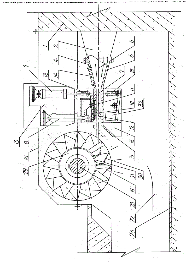
[0036] figure 1 A first embodiment of the invention is shown.

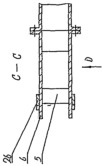
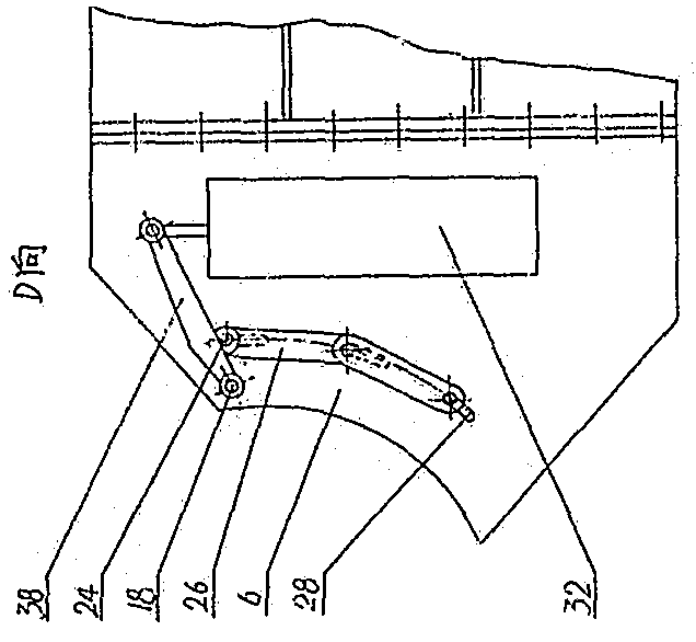
[0037]As shown in the figure: the water outlet of the pressure diversion chamber 1 is connected with an outlet 2 with a rectangular cross-sectional shape, and the water outlet of the outlet 2 is fixedly connected with a top plate 4, a bottom plate 5 and side plates 6 on both sides. Constituted outlet 7. There is a rotary valve 10 at the water outlet end of the top plate 4 through a door shaft 11 hinged device, and a flat rubber seal 12 covering its surrounding edges is provided under the rotary valve 10 and the door shaft 11 through a pressure plate device, and hinged at the top of the water outlet end of the rotary valve 10 A servomotor 8 is connected, and the other end of the servomotor 8 is hinged on the support at the top of its support plate 13, and the pressure infusion pipe of the servomotor 8 is connected with the governor hydraulic device. The middle part of the top plate 4 is provided with an inspectio...


PUM


Abstract

The invention relates to an impact type water turbine in the technical field of hydraulic electrogenerating. The water turbine is mainly composed of an ejection device and a rotation device, wherein the ejection device is mainly composed of a base plate, a top plate, lateral plates on the two sides and components such as an ejection opening formed by a rotary valve hinged to the water outlet end of the top plate or the base plate and a transmission component of the rotary valve; and the rotation device is formed by components such as a wheel disc or hub arranged on a main shaft, a plurality of blades which are arranged on the outer surface of the wheel disc or hub, the shape of the surface between the two sides is a groove, outer end guide plates arranged on the outer end faces of the groove-shaped blades, inner end guide plates arranged on the inner end faces of the groove-shaped blades and the like, wherein the shape of the surface between the two sides of each blade is in a groove shape. By means of the water turbine, the water flow pressure energy can be efficiently converted into rotary mechanical energy, and the water turbine can be suitable for low-water-head large-flow water energy resources.

Description

Technical field [0001] The invention belongs to the impact water turbine in the technical field of hydroelectric power generation, and in particular relates to a low water head, large flow and high efficiency impact water turbine. Background technique [0002] At present, the impact turbines used in hydropower production can only be used for high-head and small-flow hydropower resources, but cannot adapt to the hydropower resources that generally exist in the form of low-head and large-flow. And, the deficiency that this impulse type water turbine exists is: serious collision phenomenon will be produced when the high-speed water flow injected around the circular spray needle of circular nozzle and its internal device is concentrated to its end center, and the water flow of injection nozzle The water flow pressure energy cannot be efficiently converted into water flow energy; when there is debris jamming in the nozzle, it cannot be removed; the water discharged from the insid...

Claims


Application Information

Patent Timeline
Patent Type & Authority Applications(China)
IPC IPC(8): F03B1/04F03B1/02F03B15/20F03B11/08
CPCF03B1/02F03B15/20Y02E10/20
Inventor 黄国宏
Owner 黄国宏
Why Eureka
Try Eureka