Clutch of electric power unmanned aerial vehicle

An unmanned helicopter and clutch technology, which is applied to clutches, automatic clutches, mechanical equipment, etc., can solve the problems of affecting the flight safety of electric unmanned helicopters, excessive clearance of the triangular base, loss of power transmission of the clutch, etc. Fracture, good impact resistance, ensure the effect of power transmission

Inactive Publication Date: 2016-03-02
STATE GRID SHANDONG ELECTRIC POWER +2
View PDF6 Cites 0 Cited by
  • Summary
  • Abstract
  • Description
  • Claims
  • Application Information

AI Technical Summary

Problems solved by technology

[0004] (1) Existing electric unmanned helicopters are started by manually controlling the throttle rocker of the remote control, but the rudder volume of the throttle rocker of the remote control is relatively sensitive and human factors will cause the helicopter engine to reach a very high speed at the moment of starting, resulting in the clutch triangle base A very large relative speed is generated instantly between the clutch block and the side wall of the clutch block, and the side wall of the clutch block is subjected to a large contact stress. Continue to increase the speed until the block is in contact with the inner wall of the clutch cover. The large relative spee

Method used


Image

  • Clutch of electric power unmanned aerial vehicle
  • Clutch of electric power unmanned aerial vehicle
  • Clutch of electric power unmanned aerial vehicle

Examples


Example Embodiment

[0021] The present invention will be further described below in conjunction with the drawings and embodiments.

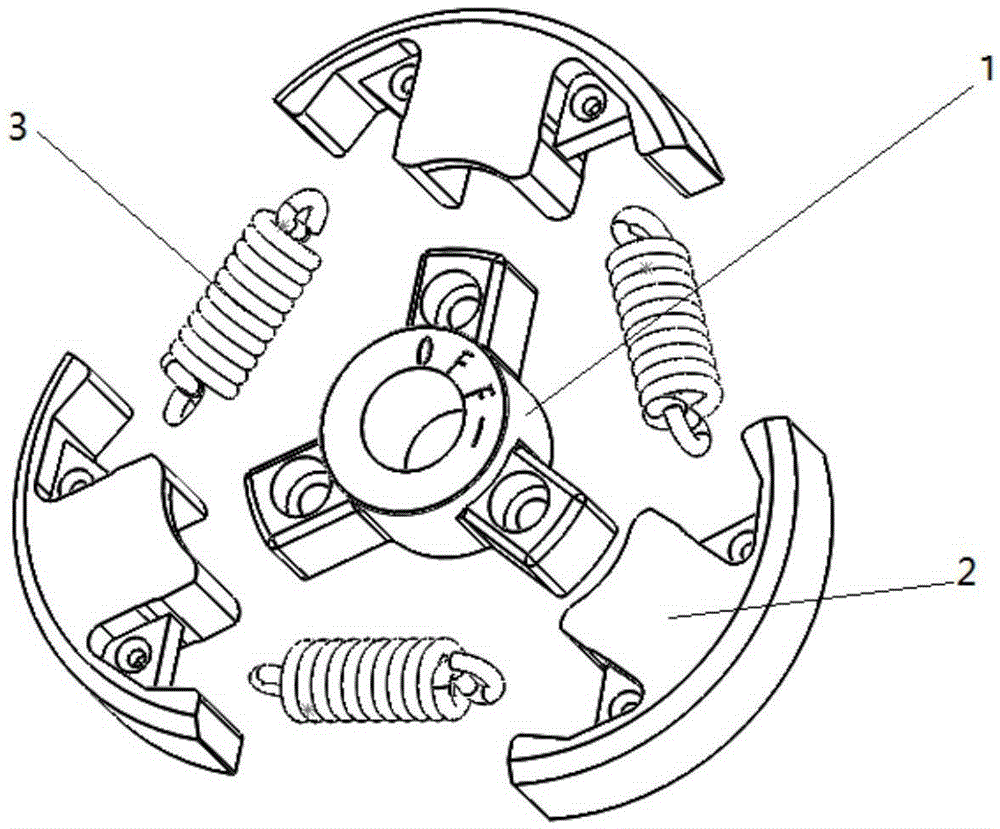
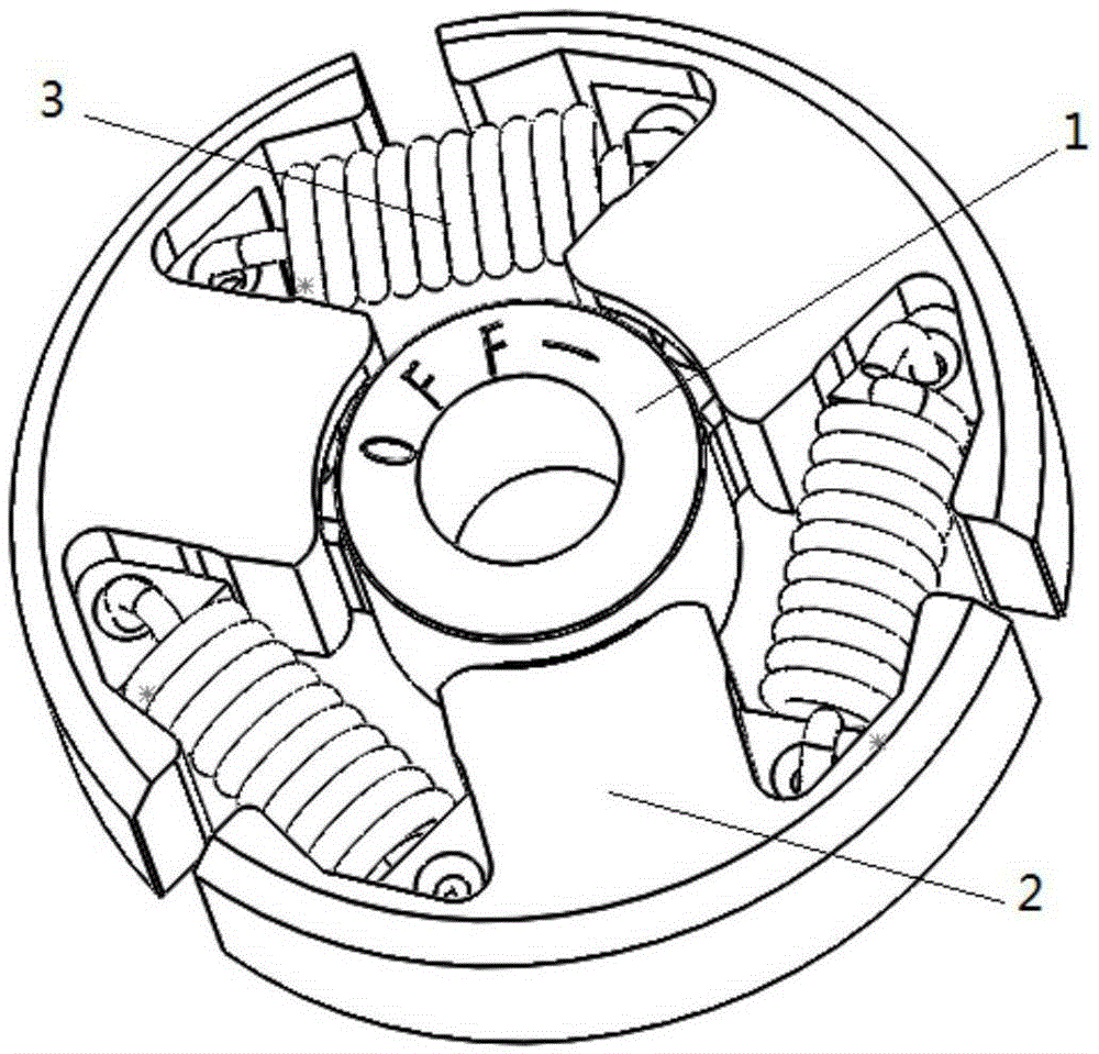
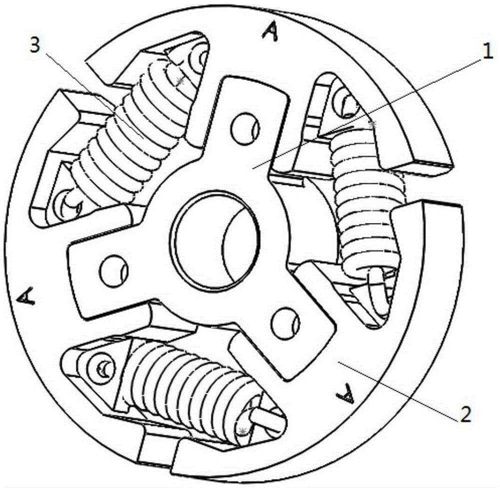
[0022] Such as figure 1 , figure 2 , image 3 , Figure 4 As shown, the present invention is an improved clutch for an electric unmanned helicopter, which includes a triangular base 1, a clutch thrower 2, a return spring 3. The center of the triangular base 1 is consistent with the center of the output shaft of the engine drive plate 5, and passes Three fastening bolts 7 are fixed to the engine driving disc, and a washer 6 is placed between the fastening bolts and the engine driving disc, and the bolts are tightened to ensure the same speed as the engine output shaft; the three clutch slingers are installed in a 120° distribution On the triangular base; the three clutch swing blocks are tightened with each other by three return springs to make the swing block close to the triangular base; the three clutch swing blocks and the triangular base are made of 40Cr material i...


PUM

PropertyMeasurementUnit
Side wall thicknessaaaaaaaaaa

Abstract

The invention discloses a clutch of an electric power unmanned aerial vehicle. The clutch comprises a triangular base, clutch swinging blocks and return springs. Through changing the structure and the material of the clutch swinging blocks of the original clutch of the electric power unmanned aerial vehicle and adopting a 40Cr material which is more wear-proof and has better shock resistance and higher hardness to replace the original powder metallurgy material, and by taking measures of increasing the thicknesses of the left side walls and the right side walls of the three clutch swinging blocks and reducing gaps between the left inner side walls and the right inner side walls of the clutch swinging blocks, great contact stress borne by the side walls of clutch swinging blocks because greater relative speeds are generated between the side walls of clutch swinging blocks and the triangular base in a starting moment is weakened effectively. In addition, the problems that a contact area is too small and the stress is concentrated due to the facts that fit clearances among the clutch swinging blocks and the triangular base are too large, and the fact that the engagement diameters of the clutch swinging blocks are not consistent with that of a clutch cover after the clutch swinging blocks are swung outwards are solved effectively. The problem that the original clutch swinging blocks break due to the fact that the original clutch swinging blocks can not bear great contact stress for a long time is solved effectively. The normal power transfer function of the clutch is ensured, and the flight safety of the electric power unmanned aerial vehicle is improved greatly.

Description

technical field [0001] The invention relates to an electric unmanned helicopter clutch. Background technique [0002] With the development of the power inspection industry, the inspection equipment has also been greatly improved. As a new type of power inspection equipment newly developed in recent years, the electric inspection unmanned helicopter has many other advantages such as portability, flexibility, and height. Advantages that detection tools do not have. The power inspection unmanned helicopter relies on the helicopter to be equipped with visible light detection equipment to take pictures of the towers. Later line inspection personnel need to rely on the inspection pictures taken by the inspection equipment to analyze the safety of the line towers. Helicopters are the carrier of inspection equipment, and the safe and stable flight of the aircraft is the premise and key to ensure the smooth progress of inspection tasks. [0003] The current power inspection unmanne...

Claims


Application Information

Patent Timeline
IPC IPC(8): F16D43/16
CPCF16D43/16F16D43/18
Inventor 李岩裴秀高王成刚王霞贾会永亓鹏亓占华王志峰李英许丹张毅
Owner STATE GRID SHANDONG ELECTRIC POWER
Why Eureka
Try Eureka