Manufacturing method of air-blowing pipeline
A manufacturing method and technology of air-blown pipes, applied in the direction of tubular objects, applications, coatings, etc., can solve the problems of not producing air-blown pipes, etc., and achieve the effect of good effect, simple manufacturing method, and excellent anti-twist performance
- Summary
- Abstract
- Description
- Claims
- Application Information
AI Technical Summary
Problems solved by technology
Method used
Image
Examples
Embodiment 1
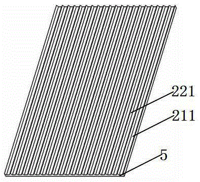
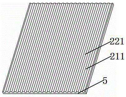
[0031] please see Figure 1 to Figure 7 , figure 1 and figure 2 Among them, the air blowing pipe is composed of the air blowing pipe body 5, the air blowing pipe convex body 221, and the air blowing pipe diversion groove 211. The air blowing pipe convex body and the air blowing pipe diversion groove are located above the air blowing pipe body and distributed at intervals. The body is protruding from the diversion groove of the air blowing pipe, and the lower surface of the air blowing pipe body is a plane; the convex body of the air blowing pipe is in the shape of a triangular prism, and the diversion groove of the air blowing pipe is in the shape of a trapezoidal cylinder.
[0032] image 3 and Figure 4 Among them, the air blowing pipe is composed of the air blowing pipe body 5, the air blowing pipe convex body 221, and the air blowing pipe diversion groove 211. The air blowing pipe convex body and the air blowing pipe diversion groove are located above the air blowing p...
Embodiment 2
[0045] please see Figure 8 to Figure 9 , and refer to Figure 1 to Figure 7 , a system for manufacturing air-blown pipes for cables, same as implementation example 1. The difference lies in the manufacturing method of the air blowing pipe. In the first step, the flat air blowing pipe body is slightly folded in half toward the direction with the air blowing pipe convex body and the air blowing pipe diversion groove, and then the air blowing pipe body is inserted into the closing channel. Then pass through the hole inside the shaping tube, then pass through the core hole and pull the air blowing pipe body, and make the plunger inside the air blowing pipe body, so that the two sides of the air blowing pipe body at the shaping end are connected at the shaping groove. The groove is heated by hot air with a hot air gun, so that the butt joints are bonded together to form a rib 6 protruding from the lower surface of the air blowing pipe body; the second step is to open the extruder...
Embodiment 3
[0049] please see Figure 10 , and refer to Figure 1 to Figure 9 , a system for manufacturing air-blown pipes for cables, same as implementation example 1. One of the differences lies in the system: a binding device is installed between the shaping end 101 and the extruder head 131. Since the binding device is the existing cable processing technology, especially the common technology of the yarn binding machine in the SZ twisted cable, Therefore, it is not drawn on the diagram.
[0050] According to the difference from the above systems, the second difference lies in the manufacturing method of the air blowing pipe: before the air blowing pipe body enters the core hole 132 of the extruder head, a binding element 9 is bound outside the blowing pipe body.
[0051] The binding element can effectively prevent the main body of the air blowing pipe from being scattered. At the same time, in the slightly melted state of the main body of the air blowing pipe, the binding element is...
PUM
 Abstract
Description
Claims
Application Information
 - R&D
- Intellectual Property
- Life Sciences
- Materials
- Tech Scout
- Unparalleled Data Quality
- Higher Quality Content
- 60% Fewer Hallucinations
Browse by: Latest US Patents, China's latest patents, Technical Efficacy Thesaurus, Application Domain, Technology Topic, Popular Technical Reports.
© 2025 PatSnap. All rights reserved.Legal|Privacy policy|Modern Slavery Act Transparency Statement|Sitemap|About US| Contact US: help@patsnap.com


