Glass substrate, liquid crystal display panel and liquid crystal display device

A technology for glass substrates and display areas, applied in instruments, nonlinear optics, optics, etc., can solve problems such as lower yield, poor product functionality, and development of large cracks

Active Publication Date: 2016-03-02
SHANGHAI TIANMA MICRO ELECTRONICS CO LTD +1
View PDF5 Cites 29 Cited by
  • Summary
  • Abstract
  • Description
  • Claims
  • Application Information

AI Technical Summary

Problems solved by technology

[0006] like image 3 As shown, if the crack detection wire 311 is placed outside the cutting tolerance C, then no small cracks can be detected, and these small cracks 313 may develop into large cracks 313 in the case of subsequent vibrations, resulting in product Poor functionality, lower yield

Method used


Image

  • Glass substrate, liquid crystal display panel and liquid crystal display device
  • Glass substrate, liquid crystal display panel and liquid crystal display device
  • Glass substrate, liquid crystal display panel and liquid crystal display device

Examples


Embodiment 1

[0021] Figure 4 A schematic structural view of a glass substrate provided in Embodiment 1 of the present invention, such as Figure 4 As shown, the glass substrate includes a display area 410 and a non-display area 420 , and the non-display area 420 of the glass substrate is provided with a crack detection wire 430 .

[0022] The crack detection wire 430 is located on at least one side of the glass substrate, and is divided into at least two sections along the extension direction of the crack detection wire 430, and the two adjacent crack detection wires along the extension direction are electrically connected, and each section The crack detection wire 430 is composed of at least two parallel wire units 431 . At least one wire unit 431 of each segment of the crack detection wire 430 is located outside the maximum deviation of cutting.

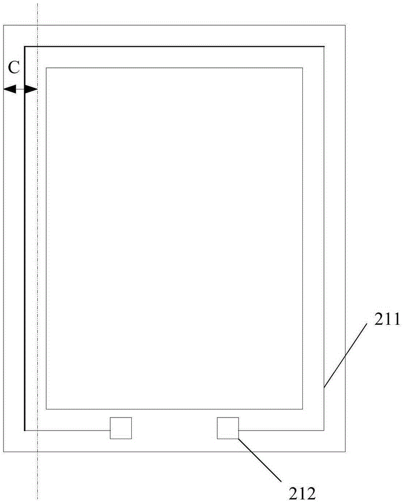
[0023] see Figure 5 , where the maximum cutting deviation C is the difference between the allowed actual cutting line 521 and the ideal c...

Embodiment 2

[0040] Figure 6 It is a schematic structural diagram of a glass substrate provided in Embodiment 2 of the present invention.

[0041] In the embodiment of the present invention, the crack detection wires located on the same side of the glass substrate can be divided into at least two sections, wherein, Figure 6 What is shown is the situation where the crack detection wires 610 on the left and right sides are divided into two sections, wherein each crack detection wire 610 includes three wire units 611 .

[0042] In addition, for each wire unit 611 on the same section of crack detection wire 610, its resistance value can be the same as that shown in the first embodiment above, or it can be different. Specifically, the resistance value of each wire unit 611 located in the same section can be It gradually increases from the edge of the glass substrate inward.

[0043] Moreover, the resistance value of each wire unit 611 can be set to be different by setting any one or several...

Embodiment 3

[0056] Figure 7 It is a schematic structural diagram of a glass substrate provided in Embodiment 3 of the present invention. The difference from the above embodiment is that the crack detection wire on the upper side of the glass substrate is divided into two sections.

[0057] Such as Figure 7 As shown, the crack detection wire 710 is divided into 6 sections along the extension direction of the crack detection wire 710 , and each crack detection wire 710 is composed of 3 parallel wire units 711 . Wherein the inner wire unit of each crack detection wire 710 is located outside the maximum cutting deviation C, assuming that the resistance value of each parallel wire unit 711 is from the outer ring to the inner ring in order: the outer wire unit is a / 3, and the middle wire unit is a / 2, the inner wire unit is a.

[0058] Cracks and cutting conditions of the glass substrate are judged by calculating the total resistance of the crack detection wires, as follows:

[0059] (1) W...


PUM


Abstract

The invention discloses a glass substrate, a liquid crystal display panel and a liquid crystal display device. The glass substrate comprises a display region and a non-display region, wherein a crack detection wire is arranged in the non-display region of the glass substrate and located on at least one edge of the glass substrate, the crack detection wire is divided into at least two sections in the extending direction, every two adjacent crack detection wire sections in the extending direction are electrically connected, each crack detection wire section is composed of at least two wire units connected in parallel, and at least one wire unit of each crack detection wire section is located on the outer side of the maximum cutting deviation. In the embodiment, through arranging crack detection wire grids, the purpose that edge cracks of the glass substrate and the length range, on the plane where the glass substrate is located, of the cracks are effectively detected is achieved.

Description

technical field [0001] The embodiments of the present invention relate to the field of liquid crystal display, and in particular to a glass substrate, a liquid crystal display panel and a liquid crystal display device. Background technique [0002] Liquid crystal display devices such as mobile phones, computers, and televisions play an increasingly important role in our daily life, and gradually become our daily necessities. In the liquid crystal display panel part of these liquid crystal display devices, the glass substrate has become one of the indispensable structures in the liquid crystal display panel due to its unique characteristics of high transparency, certain mechanical hardness and easy processing. Protect the main light-emitting monomers of the liquid crystal display panel, form the space required for pixels, and serve as a support for the liquid crystal display panel. [0003] In the production process of liquid crystal display panels, there are multiple units ...

Claims


Application Information

Patent Timeline
Patent Type & Authority Applications(China)
IPC IPC(8): G02F1/13
CPCG02F1/1309
Inventor 赵剑
Owner SHANGHAI TIANMA MICRO ELECTRONICS CO LTD
Why Eureka
Try Eureka