Touch and liquid crystal display integration module

A liquid crystal display and integrated module technology, which is applied in optics, instruments, electrical digital data processing, etc., can solve the problems of limited manufacturers or merchants, unfavorable development, and high threshold, so as to simplify the production process and reduce adhesion The effect of loosening and optimizing product performance

Inactive Publication Date: 2016-03-02
东莞通华液晶有限公司
View PDF6 Cites 4 Cited by
  • Summary
  • Abstract
  • Description
  • Claims
  • Application Information

AI Technical Summary

Problems solved by technology

Due to the requirements of product technology and yield rate, the production process and application of the existing touch screen make the corresponding application difficult or meet the complex process and processing requirements, which does not make the manufacturing threshold very high. For general touch screen and As far as display manufacturers are concerned, the technical difficulties to be overcome are huge, which cannot satisfy their development and actual interests.
Moreover, for high-precision, high-pixel touch LCD screens, which are designed using the existing popular TFT technology, as the size of the large screen increases, the required chip processing capacity is greater because of the large pixel array. As the multiple increases, the number of embedded touch controllers also increases, which brings that the quality of the touch LCD screen cannot be guaranteed, and the production cost and technical difficulty increase, and the manufacturers or merchants of production are limited, which is not conducive to the development of the market develop

Method used


Image

  • Touch and liquid crystal display integration module

Examples


Embodiment Construction

[0018] Further illustrate the present invention below in conjunction with accompanying drawing.

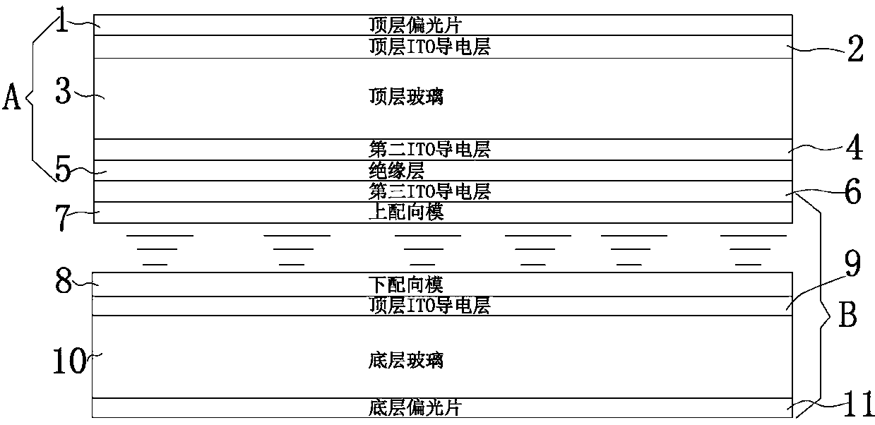
[0019] Such as figure 1 It shows a specific embodiment of the present invention, a touch and liquid crystal display integrated module, including a top polarizer 1, a top ITO conductive layer 2, a top glass 3, a touch liquid crystal group, and a bottom ITO conductive layer arranged in sequence from top to bottom 9. Bottom glass 10 and bottom polarizer 11; wherein, the touch liquid crystal group includes a second ITO conductive layer 4, an insulating layer 5, a third ITO conductive layer 6, and a liquid crystal layer, and the second ITO conductive layer 4 and the first The insulating layer 5 is arranged between the three ITO conductive layers 6, and the liquid crystal layer is arranged at the lower end of the third ITO conductive layer 6; the liquid crystal layer includes an upper alignment film 7 and a lower alignment film 8, and the upper alignment film There is a certain distanc...


PUM

PropertyMeasurementUnit
Thicknessaaaaaaaaaa
Widthaaaaaaaaaa

Abstract

The invention discloses a touch and liquid crystal display integration module comprising a top polarizer, a top ITO conductive layer, top glass, a touch liquid crystal group, a bottom ITO conductive layer, bottom glass, and a bottom polarizer. The touch liquid crystal group includes a second ITO conductive layer, an insulating layer, a third ITO conductive layer and a liquid crystal layer, wherein the insulating layer is arranged between the second ITO conductive layer and the third ITO conductive layer, and the liquid crystal layer is arranged on the lower end of the third ITO conductive layer. The liquid crystal layer includes an upper alignment film, a lower alignment film and liquid crystal molecules. The top ITO conductive layer and the second ITO conductive layer form a touch function control part. The third ITO conductive layer is a liquid crystal display control part, and the control part contains a signal electrode for controlling liquid crystal display. The bottom ITO conductive layer is provided with a scanning electrode lead for liquid crystal display. The signal electrode and the scanning electrode for liquid crystal display constitute a control electrode of the liquid crystal layer. The display integration module of the invention is touch-sensitive and has a simple structure. The production process is simplified, and the production cost is reduced.

Description

technical field [0001] The invention relates to the field of liquid crystal display, in particular to a touch and liquid crystal display integrated module. Background technique [0002] As the latest human-computer interaction technology, the touch screen is a transparent input system. As long as the user touches the text or pattern on the display screen with a finger or an electronic pen, the user can get rid of the excessive dependence on the mouse and keyboard, making the human-computer interaction more straightforward. The existing touch screens include two types of resistive screens and capacitive screens. However, for optimizing product performance, resistive screens can no longer meet the needs. It has become an inevitable trend to choose capacitive screens. [0003] The capacitive touch screen works by using the current induction of the human body. The capacitive touch screen is usually a four-layer composite glass screen. When the user's finger touches the capacit...

Claims


Application Information

Patent Timeline
IPC IPC(8): G02F1/1333G06F3/041G06F3/044
CPCG02F1/13338G06F3/0412G06F3/044
Inventor 潘翼辉
Owner 东莞通华液晶有限公司
Why Eureka
Try Eureka