Direct current (DC)/alternating current (AC) conversion device, direct current/ direct current conversion device and constant current driving device

A conversion device and constant current drive technology, which is applied in the direction of output power conversion device, high-efficiency power electronic conversion, DC power input conversion to DC power output, etc., can solve the problems of reduced efficiency of driving equipment, complex circuit structure, unfavorable implementation, etc. , to achieve the effect of reducing the volume of the device, the number of components and parts, and ensuring the safety of use

Inactive Publication Date: 2016-03-02
OPPLE LIGHTING
View PDF5 Cites 7 Cited by
  • Summary
  • Abstract
  • Description
  • Claims
  • Application Information

AI Technical Summary

Problems solved by technology

[0003] At present, the LED driving schemes to achieve high power factor include pre-amplified active power factor correction (APFC) circuit and single-stage active power factor correction constant current scheme, etc. However, the above schemes also have cost Significant increase and decrease in efficiency of driving equipment, and its circuit structure is usually more complicated, which is not conducive to the implementation

Method used


Image

  • Direct current (DC)/alternating current (AC) conversion device, direct current/ direct current conversion device and constant current driving device
  • Direct current (DC)/alternating current (AC) conversion device, direct current/ direct current conversion device and constant current driving device
  • Direct current (DC)/alternating current (AC) conversion device, direct current/ direct current conversion device and constant current driving device

Examples


Embodiment Construction

[0026] Exemplary embodiments of the present disclosure will be described in more detail below with reference to the accompanying drawings. Although exemplary embodiments of the present disclosure are shown in the drawings, it should be understood that the present disclosure may be embodied in various forms and should not be limited by the embodiments set forth herein. Rather, these embodiments are provided for more thorough understanding of the present disclosure and to fully convey the scope of the present disclosure to those skilled in the art.

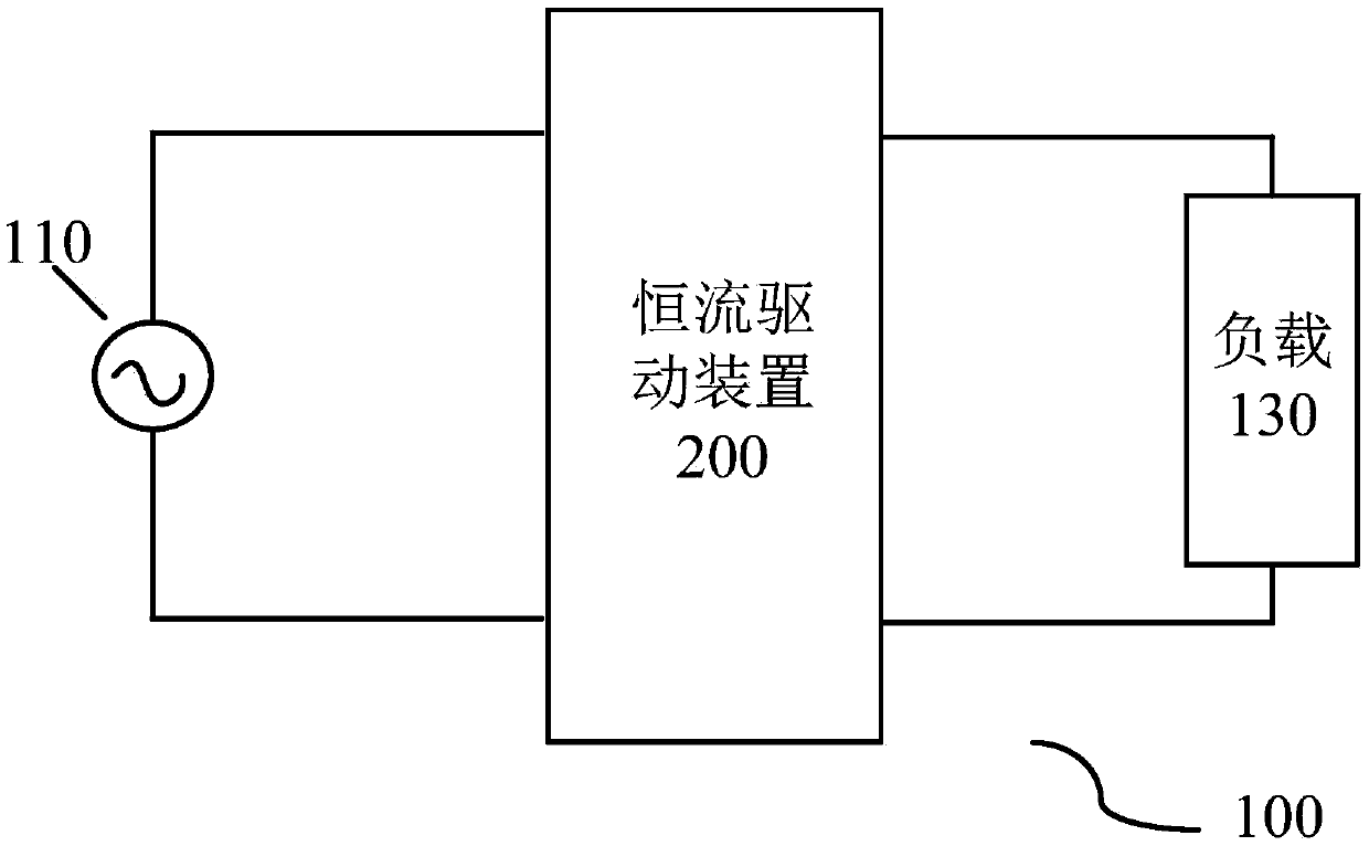
[0027] figure 1 A structural block diagram of an illumination system 100 according to an exemplary embodiment of the present invention is shown. The lighting system 100 may include a mains power supply 110 , a constant current drive device 200 and a load 130 . The mains power supply 110 may provide different unrectified AC mains voltages according to various implementations, such as 220V AC mains frequency. The load 130 may be an ...


PUM


Abstract

The present invention discloses a direct current (DC) / alternating current (AC) conversion device. The direct current (DC) / alternating current (AC) conversion device comprises a charge pump circuit, a half-bridge resonance device and a control device; the charge pump circuit is suitable for receiving direct current input voltage and alternating current feedback from the half-bridge resonance device, and a DC bus voltage is output after power factor correction; the half-bridge resonance device is suitable for receiving the DC bus voltage, an AC output voltage is output through conversion, the half-bridge resonance device includes a half-bridge inversion circuit and a resonance tank circuit, and the half-bridge inversion circuit consists of a switch and is suitable for receiving the DC bus voltage and a switching signal from the control device so as to output a pulse voltage to the resonance tank circuit; the resonance tank circuit is suitable for receiving the pulse voltage, an AC output voltage is output through resonance, and the resonance tank circuit is also suitable for output AC feedback to the charge pump circuit; and the control device is suitable for generating the switching signal and controlling the AC output voltage according to the switching signal, wherein the switching signal is configured to indicate on and off of the switch. The present invention further discloses a direct current / direct current conversion device and a constant current driving device.

Description

technical field [0001] The invention relates to the technical field of integrated circuits, in particular to a DC / AC conversion device, a DC / DC conversion device and a constant current drive device. Background technique [0002] With the rapid development of power electronics technology and LED light sources, LED light sources are widely used in various lighting needs due to their high luminous efficiency, low power consumption, long service life, and strong safety and reliability. But at the same time, national standards, European standards, etc. have certain requirements for the power factor (PF value) of LED lighting products. In particular, the power factor requirements for LED lighting products are higher in engineering projects with a large number of applications. [0003] At present, the LED driving schemes to achieve high power factor include pre-amplified active power factor correction (APFC) circuit and single-stage active power factor correction constant current s...

Claims


Application Information

Patent Timeline
Patent Type & Authority Applications(China)
IPC IPC(8): H02M7/5387H02M7/5383H02M3/335H02M1/44
CPCH02M1/44H02M3/33592H02M7/5383H02M7/53873Y02B70/10
Inventor 朱元孙伟光
Owner OPPLE LIGHTING
Why Eureka
Try Eureka