Pipe components and methods of manufacture

A technology of riser components and flexible pipes, applied in the direction of pipes/pipe joints/fittings, drill pipes, casings, etc., can solve problems such as large oscillation motion, failure of standpipe system, etc., to prolong life and suppress vortex-induced vibration Effect

Inactive Publication Date: 2016-03-02
GE OIL & GAS UK LTD
View PDF4 Cites 4 Cited by
  • Summary
  • Abstract
  • Description
  • Claims
  • Application Information

AI Technical Summary

Problems solved by technology

If the frequency of VIV is close to the resonant frequency of the pipeline including the buoyancy means in its installed configuration, the riser will experience large oscillatory motions and this can lead to failure of the riser system

Method used


Image

  • Pipe components and methods of manufacture
  • Pipe components and methods of manufacture
  • Pipe components and methods of manufacture

Examples


Embodiment Construction

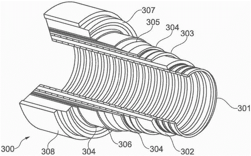
[0040] Throughout this specification reference is made to flexible pipe. It should be understood that flexible pipe is an assembly of a portion of a pipe body and one or more end fittings in each of which a respective end of the pipe body terminates. image 3 It is shown how the tube body 300 is formed from a combination of layered materials forming a pressurized conduit according to an embodiment of the present invention. although image 3 Some specific layers are shown in , but it should be understood that the invention is broadly applicable to coaxial pipe body structures comprising two or more layers fabricated from a wide variety of possible materials. It should be further noted that layer thicknesses are shown for illustrative purposes only.

[0041] Such as image 3 As shown, the tube body includes an optional carcass layer 301 . The carcass provides an interlocking construction that can be used as the innermost layer to fully or partially prevent rupture of the inn...


PUM

PropertyMeasurementUnit
lengthaaaaaaaaaa
lengthaaaaaaaaaa
lengthaaaaaaaaaa

Abstract

A connector assembly including a body portion (824) for locating over a flexible pipe and arranged to be connectible to or formed integrally with one or more buoyancy compensating elements (800), and one or more protrusion (826) extending from the body portion (824) and arranged to reduce or interrupt vortex induced vibrations in water surrounding the flexible pipe in use.

Description

technical field [0001] The present invention relates to components for flexible pipe and methods of making the components. In particular, but not exclusively, the invention relates to a component that can be coupled to a flexible pipe and connected to a buoyancy compensating element or between two buoyancy compensating elements. Background technique [0002] Traditionally, production fluids, such as oil and / or gas and / or water, have been transported from one location to another using coiled tubing. Coiled tubing is particularly useful in connecting a subsea location (which may be deep water of about 1000 meters or more or shallow water of about 250 to 1000 meters) to a sea level location. The tube may have an inner diameter typically up to about 0.6 meters. Flexible pipe is typically formed as an assembly of a flexible pipe body and one or more end fittings. The pipe body is typically formed as a combination of layered materials forming a pressurized conduit. The tube st...

Claims


Application Information

Patent Timeline
Patent Type & Authority Applications(China)
IPC IPC(8): E21B17/01E21B17/02F16L1/24
CPCF16L1/15F16L1/123F16L1/24Y10T403/54Y10T29/494
Inventor 袁家北谭志敏侯玉成张艳秋
Owner GE OIL & GAS UK LTD
Why Eureka
Try Eureka