
Laser processing device and laser head anti-collision assembly thereof

A laser head and anti-collision technology, which is applied in the fields of laser welding and laser cutting, can solve problems such as easy jamming of anti-collision components, and achieve the effect of improving reliability and reducing damage

Inactive Publication Date: 2016-03-09
HANS LASER TECH IND GRP CO LTD
View PDF9 Cites 6 Cited by
  • Summary
  • Abstract
  • Description
  • Claims
  • Application Information

AI Technical Summary

Problems solved by technology

[0005] Based on this, it is necessary to provide a laser processing equipment and its laser head anti-collision component for the problem that the anti-collision component is easily stuck when it is deflected by impact

Method used


Image

  • Laser processing device and laser head anti-collision assembly thereof
  • Laser processing device and laser head anti-collision assembly thereof
  • Laser processing device and laser head anti-collision assembly thereof

Examples


Embodiment Construction

[0028] In order to facilitate the understanding of the present invention, the laser processing equipment and its laser head anti-collision assembly will be described below in a more comprehensive manner with reference to related drawings. The preferred embodiment of the laser processing equipment and its laser head anti-collision assembly is shown in the drawings. However, the laser processing equipment and its laser head anti-collision assembly can be implemented in many different forms and are not limited to the embodiments described herein. On the contrary, the purpose of providing these embodiments is to make the disclosure of the laser processing equipment and its laser head anti-collision assembly more thorough and comprehensive.

[0029] Unless otherwise defined, all technical and scientific terms used herein have the same meaning as commonly understood by those skilled in the technical field of the present invention. The terms used in the description of the laser process...


PUM


Abstract

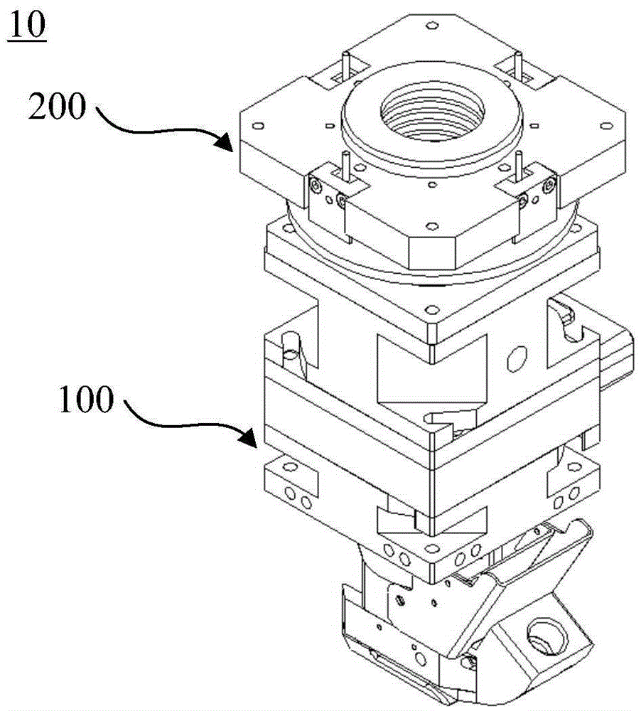
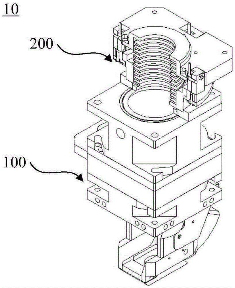
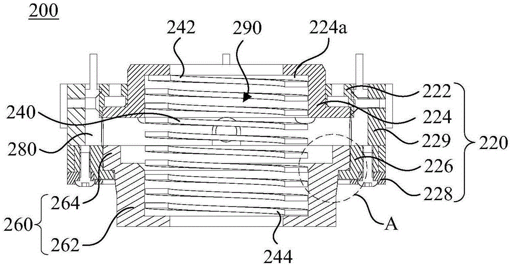
The invention relates to a laser processing device and a laser head anti-collision assembly thereof. The laser head anti-collision assembly comprises installation bases, elastic pieces, connecting pieces and sensors. The elastic pieces are located in containing spaces of the installation bases. The first ends of the elastic pieces are in butt joint with the installation bases. The connecting pieces comprise body parts and clamping parts. The body parts are in a barrel shape, and the clamping parts are in a circular ring shape and protrude out of the body parts. The connecting pieces are installed on the installation bases. The clamping parts are connected with the installation bases in a clamping manner. At least part of the body parts penetrate out of the containing spaces through installation openings, and the ends, away from the installation bases, of the body parts are used for being connected with laser heads. The second ends of the elastic pieces are in butt joint with the bottoms of the body parts. The connecting pieces can stretch, contract and rotate at the installation openings. The outer surfaces of the parts, close to the installation bases at the installation openings, of the body parts are in an arc face shape. The outer surfaces of the parts, close to the installation bases at the installation openings, of the body parts are in an arc shape face shape. When a laser head is subjected to impacts to deflect, the phenomenon that the connecting pieces are blocked by the installation bases can be avoided, and reliability of the laser head anti-collision assembly is improved.

Description

Technical field [0001] The invention relates to the technical field of laser cutting and laser welding, in particular to a laser processing equipment and its laser head anti-collision component. Background technique [0002] Laser processing is to irradiate the laser to the object to be processed, and use the effect of the laser on the object to change the properties, properties and shape of the material, so as to achieve cutting processing, welding processing, etc. [0003] Laser head is a key component in laser processing equipment, with high price and poor impact resistance. When the laser head is processing an object, if the laser head collides with the workpiece or tooling due to the negligence of the processing personnel or programming negligence, the laser head is easily damaged. Therefore, it is necessary to design a device to protect the laser head in the event of a collision between the laser head and the workpiece. [0004] The laser head is usually protected by magnetic...

Claims


Application Information

Patent Timeline
IPC IPC(8): B23K26/70B23K26/38
CPCB23K37/006B23K26/38
Inventor 成龙肖祥初张波肖俊君陈根余陈燚高云峰
Owner HANS LASER TECH IND GRP CO LTD
Learn More