
Motor brake system

An engine braking and engine technology, applied in engine components, machine/engine, valve control, etc., can solve the problems of large push rod load, large contact stress, camshaft and tappet wear, etc., and achieve the effect of solving wear problems.

Inactive Publication Date: 2016-03-09
WEICHAI POWER CO LTD
View PDF6 Cites 3 Cited by
  • Summary
  • Abstract
  • Description
  • Claims
  • Application Information

AI Technical Summary

Problems solved by technology

This will lead to excessive load on the pushrod, excessive contact stress between the camshaft and tappet, causing wear of the camshaft and tappet

Method used


Image

  • Motor brake system
  • Motor brake system
  • Motor brake system

Examples


Embodiment Construction

[0022] The specific implementation manners of the present invention will be further described in detail below in conjunction with the accompanying drawings and embodiments. The following examples are used to illustrate the present invention, but are not intended to limit the scope of the present invention.

[0023] In the description of the present invention, it should be noted that the terms "center", "longitudinal", "transverse", "upper", "lower", "front", "rear", "left", "right", " The orientations or positional relationships indicated by "vertical", "horizontal", "top", "bottom", "inner", "outer", etc. are based on the orientation or positional relationships shown in the drawings, and are only for the convenience of describing the present invention and simplifying Describes, but does not indicate or imply that the device or element referred to must have a specific orientation, be constructed in a specific orientation, and operate in a specific orientation, and therefore sh...


PUM


Abstract

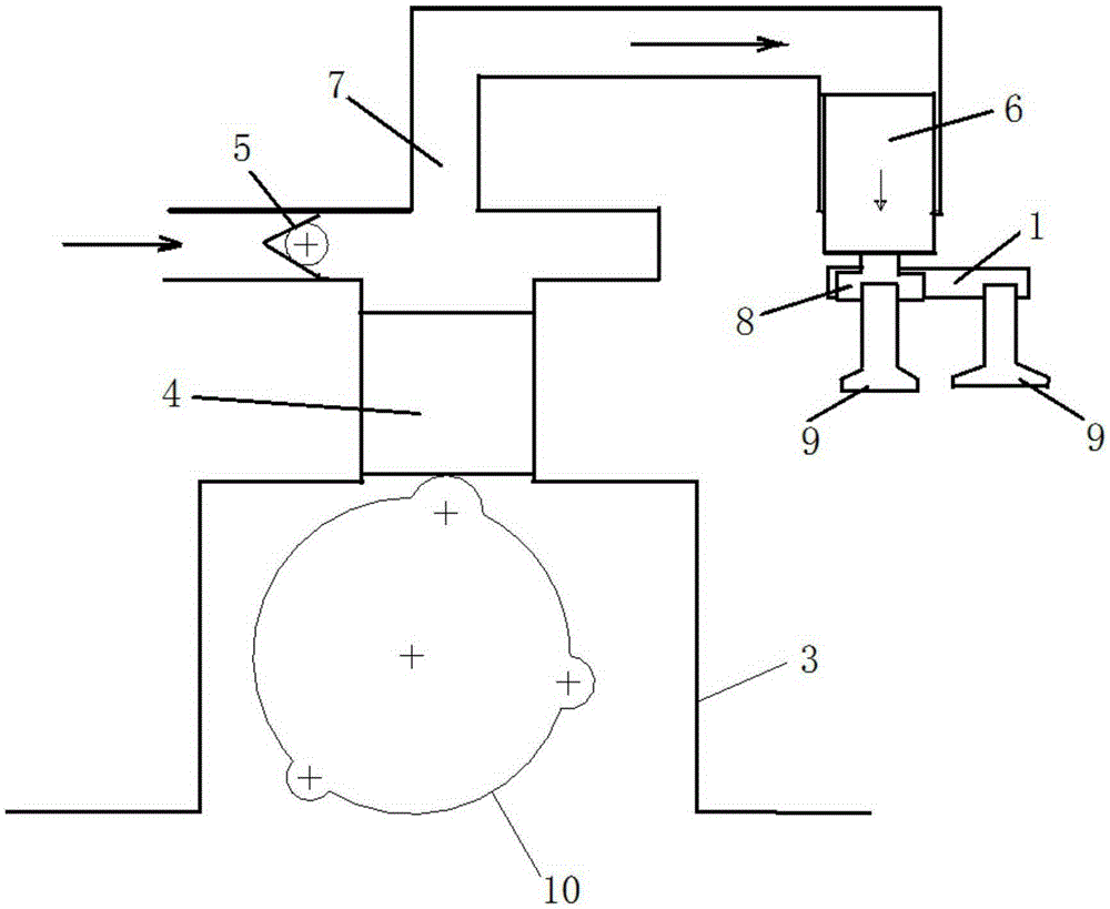
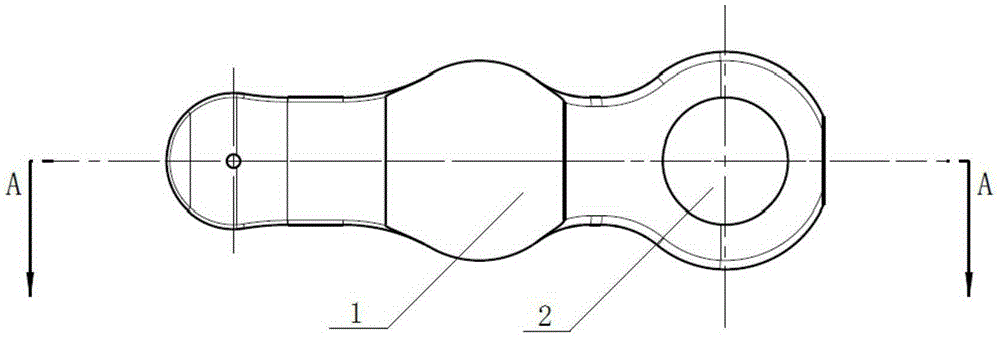
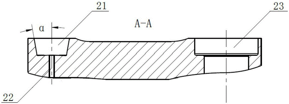
The invention relates to the field of motor braking, and discloses a motor brake system, which comprises a motor body and further comprises a brake pump assembly, a valve bridge assembly and a brake piston; the brake pump assembly and the valve bridge assembly are arranged on the motor body; the brake pump assembly comprises a pump body connected with the brake piston by a master oil pipe and provides hydraulic oil for the brake piston; a cam is arranged in an inner cavity of the pump body; a plunger is arranged above the cam and is driven to move up and down by the rotation of the cam; the valve bridge assembly comprises a valve bridge body, an execution pin and a valve rod; the valve bridge body is provided with a guide hole; the valve rod is arranged in the guide hole by the execution pin positioned below the brake piston. High oil pressure can be created by the brake pump arranged on the motor so as to drive the brake piston to open the brake valve, a high load generated during braking is transferred and the problem of wear of a cam shaft and a tappet in an air distribution mechanism is solved.

Description

technical field [0001] The invention relates to the field of engine braking, in particular to an engine braking system. Background technique [0002] When the engine is braking, it is necessary to rely on a set of actuators to open the exhaust valve near the compression top dead center to discharge the compressed gas to achieve engine braking. [0003] The braking design of the existing diesel engine is usually to add a braking cam to the original cam. In order to obtain high braking power, the requirement for high braking pressure is relatively high. When braking, opening the exhaust valve needs to overcome the high cylinder pressure, so the force to open the valve is very large. Due to the integration of the actuator on the valve bridge, the forces acting on the pushrod and camshaft greatly exceed the force required to open the valve. This will lead to excessive load on the pushrod, excessive contact stress between the camshaft and tappet, and wear of the camshaft and ta...

Claims


Application Information

Patent Timeline
IPC IPC(8): F01L13/06
CPCF01L13/06F01L2760/005
Inventor 李文广王刚乔军
Owner WEICHAI POWER CO LTD
Learn More