
Ultrasonic guided wave transducer that can be built into the inspection pipeline

A technology for guiding ultrasonic waves and detecting pipelines, which is applied in pipeline systems, using sound waves/ultrasonic waves/infrasonic waves to analyze solids, and using sound waves/ultrasonic waves/infrasonic waves for material analysis, etc. It is inconvenient to place the probe on the outer surface of the profile, and the detection efficiency is low, so as to achieve the effects of adjustable pressure, high sensitivity, and high energy conversion efficiency

Active Publication Date: 2018-04-10
HANGZHOU ZHEJIANG UNIV JINGYI ELECTROMECHANICAL TECH ENG
View PDF6 Cites 0 Cited by
  • Summary
  • Abstract
  • Description
  • Claims
  • Application Information

AI Technical Summary

Problems solved by technology

However, for some special occasions, for example, it is inconvenient to place probes on the outer surface of brackets or special-shaped materials, and the small outer diameter cannot achieve better coupling effects, etc., so it is impossible to use external construction probes for detection.
In addition, the external installation of most non-destructive testing probes is relatively complicated at present, and it often takes several processes to complete, and the efficiency of batch testing is low

Method used


Image

  • Ultrasonic guided wave transducer that can be built into the inspection pipeline
  • Ultrasonic guided wave transducer that can be built into the inspection pipeline
  • Ultrasonic guided wave transducer that can be built into the inspection pipeline

Examples


Embodiment Construction

[0026] The present invention will be further described in detail below with reference to the embodiments and accompanying drawings. Obviously, this is an embodiment of the present invention but not limited thereto. Based on the embodiments of the present invention, all other embodiments obtained by those skilled in the art without making creative efforts belong to the protection scope of the present invention.

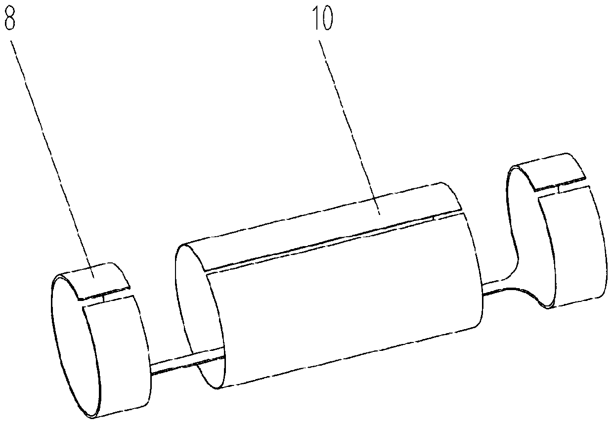
[0027] Such as figure 1 As shown, the present invention includes a connector 1 connected in sequence, an electrical separation tee 2 and a connecting pipe 4, and an ultrasonic guided wave transducer mechanism connected at the end of the connecting pipe 4 and extending into the metal pipe 2 to be detected. The wave transducing mechanism includes a magnetic coil structure and a magnetostrictive strip 10 . The magnetostrictive strip 10 is used to generate and receive guided waves. A permanent magnet is used to magnetize the strip in the axial direction, leaving residual ...


PUM

PropertyMeasurementUnit
diameteraaaaaaaaaa

Abstract

The present invention discloses an ultrasonic guided-wave energy transducer capable of being arranged in a detection pipeline. The ultrasonic guided-wave energy transducer includes a connector assembly, an electrical separation tee, a connecting pipe and an ultrasonic guided-wave energy transducer mechanism, the connector assembly, the electrical separation tee and the connecting pipe are sequentially connected, the ultrasonic guided-wave energy transducer mechanism is arranged at the end part of the connecting pipe and extends into the interior of a metal pipe, a ventilation end shaft and a seal end shaft are integrally connected by a core-connection shaft, the ventilation end shaft and the seal end shaft are respectively sleeved by two compressing sleeves, an electromagnetic coil structure is arranged on the core-connection shaft between the ventilation end shaft and the seal end shaft; a silicone tube sleeves outside the electromagnetic coil structure, both ends of the silicone tube are respectively pressed between one side compression sleeve and the ventilation end shaft and the other side compression sleeve and the seal end shaft; a magnetostriction strip material is welded on to a strip material supporting frame, two fixing rings of the strip material supporting frame respectively sleeve the two compressing sleeves. The ultrasonic guided-wave energy transducer can be arranged in a pipeline for detection, in the external, only simple gas charge and discharge is needed, the nondestructive testing whole process is simplified, the detection efficiency is improved, and the ultrasonic guided-wave energy transducer is suitable for batches of detection tasks.

Description

technical field [0001] The invention relates to the technical field of ultrasonic guided wave nondestructive testing, in particular to an ultrasonic guided wave transducer that can be built into a testing pipeline. Background technique [0002] With the development of social industry, the industrial and civil use of pipelines has increased dramatically. In order to ensure the safe use of pipelines, the task of pipeline inspection is becoming increasingly heavy. However, most of the ultrasonic guided wave transducers currently on the market for non-destructive testing of pipelines are coated on the outer surface of steel pipes or other profiles for testing. However, for some special occasions, such as it is inconvenient to place probes on the outer surface of brackets or special-shaped materials, and the small outer diameter cannot achieve better coupling effects, etc., it is impossible to use external construction probes for detection. In addition, the external installation...

Claims


Application Information

Patent Timeline
Patent Type & Authority Patents(China)
IPC IPC(8): G01N29/04F17D5/06
CPCF17D5/06G01N29/043
Inventor 骆苏军陈会明张小伟赵翔
Owner HANGZHOU ZHEJIANG UNIV JINGYI ELECTROMECHANICAL TECH ENG
Learn More