
Rotor of rotating electrical machine

A technology of rotating electrical machines and rotors, applied in the field of rotors of rotating electrical machines, can solve the problems of reducing the pressing-fixing force, the ring cannot be pressed to the predetermined position, and the number increases, so as to avoid the increase in the number of parts

Active Publication Date: 2016-03-09
DENSO CORP
View PDF8 Cites 0 Cited by
  • Summary
  • Abstract
  • Description
  • Claims
  • Application Information

AI Technical Summary

Problems solved by technology

[0010] Therefore, when the ring is press-fitted on the other shaft end portion of the shaft, foreign matter may be caught and may cause a problem of lowering the pressing-fixing force or a problem that the ring cannot be pressed to a predetermined position
[0011] In addition, in the case of Publication No. 11-69675, the number of parts increases due to the use of rings, and there is also a problem of higher cost

Method used


Image

  • Rotor of rotating electrical machine
  • Rotor of rotating electrical machine
  • Rotor of rotating electrical machine

Examples


no. 1 example

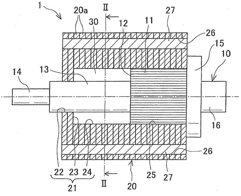
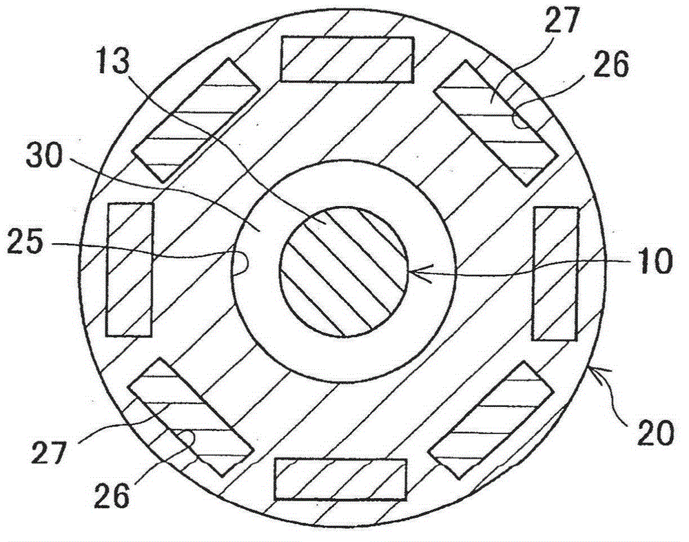
[0029] will refer to figure 1 and 2 The rotor of the rotary electric machine according to the first embodiment is described.

[0030] The rotor 1 of the rotating electrical machine of the first embodiment is used for a rotating electrical machine such as, for example, a motor for a vehicle, and is housed in a casing of the rotating electrical machine while being rotatably provided on the inner periphery of a stator (not shown). on the side.

[0031] Such as figure 1 As shown, the rotor 1 has a shaft 10 having a knurled portion 11 on its outer peripheral surface; and a rotor core 20 having fitting holes coaxially fitted and fixed on the outer peripheral surface of the shaft 10 twenty one.

[0032] The shaft 10 is formed in a solid elongated shaft-like shape made of iron-based metal.

[0033] defined by figure 1 In the axial direction from right to left, the direction in which the shaft 10 is inserted into the fitting hole 21 of the rotor core 20 is taken as the shaft inse...

no. 2 example

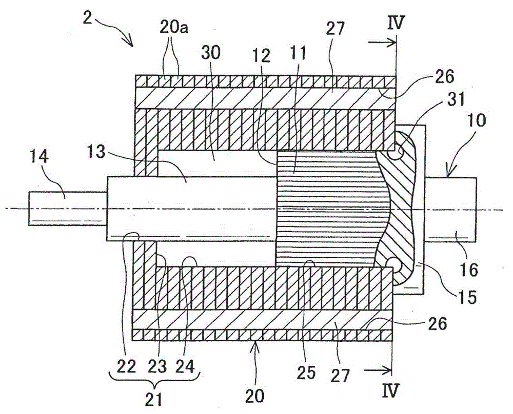
[0075] will refer to image 3 and 4 The rotor 2 of the rotating electric machine according to the second embodiment is described.

[0076] Although the rotor 2 of the second embodiment has the same basic configuration as that of the first embodiment, it differs from the rotor 1 of the first embodiment in that a groove-shaped space portion 31 formed on the shaft 10 is added.


PUM


Abstract

Disclosed is a rotor of a rotating electrical machine. The rotor 1 includes a shaft 10, and a rotor core 20 that is fitted and fixed to the shaft 10. The shaft 10 includes a knurled portion 11 on an end side and a small-diameter portion 13 formed in a tip side via a first stepped surface 12. The rotor core 20 includes a small diameter hole 22 formed in a tip side end portion of the fitting hole 21 press-fitted onto the small diameter portion 13, a large diameter hole 24 formed in an end side of the small diameter hole 22 via a second stepped surface 23, and a press-fitting portion 25 press-fitted onto the knurled portion 11 and is formed on an end side end portion of the large diameter hole 24. A space part 30 is disposed between the first stepped surface 12 and the second stepped surface 23.

Description

technical field [0001] The present invention relates to a rotor used as a rotating electrical machine of an engine or generator mounted on a vehicle such as, for example, a hybrid vehicle or an electric vehicle. Background technique [0002] Conventionally, as a rotating electrical machine used and mounted on a vehicle, a field rotation type synchronous motor (hereinafter referred to as an IPM motor) having a structure in which permanent magnets are embedded in a rotor is known. [0003] Since it is possible to utilize both the reluctance torque generated by the magnetization of the rotor and the reluctance torque generated by the magnetization of the permanent magnets, the IPM motor is highly efficient and thus preferably used for a hybrid vehicle or an electric vehicle, or the like. [0004] Such an IPM motor includes a stator serving as an armature and a rotor serving as a field system arranged to face the stator in a radial direction. [0005] In Japanese Patent Applica...

Claims


Application Information

Patent Timeline
Patent Type & Authority Applications(China)
IPC IPC(8): H02K1/28
CPCH02K1/28H02K1/276
Inventor 生田裕之
Owner DENSO CORP
Learn More