Radio frequency matching circuit, and method for debugging radio frequency matching circuit

A technology of RF matching and debugging method, applied in the field of communication, can solve the problems of increased RF signal reflection, non-convergence of the impedance matching diagram, and large RF signal loss, so as to reduce the reflected power, improve the debugging effect, and improve the performance.

Inactive Publication Date: 2016-03-09
PHICOMM (SHANGHAI) CO LTD
View PDF3 Cites 2 Cited by
  • Summary
  • Abstract
  • Description
  • Claims
  • Application Information

AI Technical Summary

Problems solved by technology

[0008] In view of the above-mentioned shortcomings of the prior art, the purpose of the present invention is to provide a radio frequency matching circuit and a debugging method for the radio frequency matching circuit, which are used to solve the problem that the impedance matching diagram of the debugging does not converge when debugging the radio frequency impedance matching in the prior art. , the reflection of radio frequency signal increases at some frequency points, and the problem of large loss of radio frequency signal

Method used


Image

  • Radio frequency matching circuit, and method for debugging radio frequency matching circuit
  • Radio frequency matching circuit, and method for debugging radio frequency matching circuit

Examples


Embodiment Construction

[0038] Embodiments of the present invention are described below through specific examples, and those skilled in the art can easily understand other advantages and effects of the present invention from the content disclosed in this specification. The present invention can also be implemented or applied through other different specific implementation modes, and various modifications or changes can be made to the details in this specification based on different viewpoints and applications without departing from the spirit of the present invention. It should be noted that, in the case of no conflict, the following embodiments and features in the embodiments can be combined with each other.

[0039] It should be noted that the diagrams provided in the following embodiments are only schematically illustrating the basic ideas of the present invention, and only the components related to the present invention are shown in the diagrams rather than the number, shape and shape of the compo...


PUM


Abstract

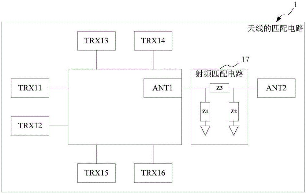
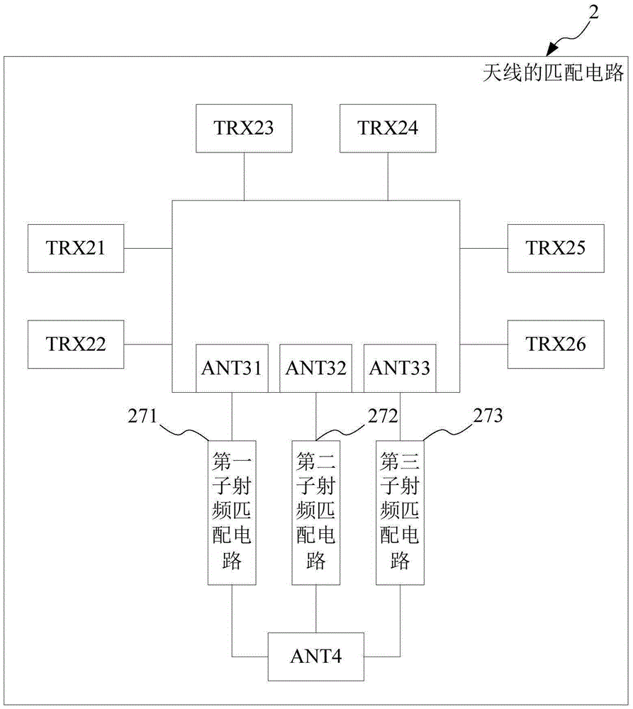
The invention provides a radio frequency matching circuit and a method for debugging the radio frequency matching circuit. The radio frequency matching circuit includes more than two sub radio frequency matching circuits, one end of each sub radio frequency matching circuit is connected with a sub signal output end, and the other end is connected with an input end of an antenna; and a signal output by each of the sub signal output ends has a different frequency range. Thus signals output by an output end of a radio frequency converter are output through more than two sub signal output ends according to difference of the frequency ranges, then impedance in the corresponding frequency range is debugged through the sub radio frequency matching circuit connected with the sub signal output end, so that a radio frequency engineer can perform matching debugging in a relatively small frequency range, the debugging difficulty is lowered, the degree of convergence of a Smith chart is improved, the reflection power is reduced, and a debugging effect is improved, thereby improving the radio frequency performance of a mobile terminal.

Description

technical field [0001] The invention relates to the technical field of communication, in particular to a radio frequency matching circuit and a debugging method for the radio frequency matching circuit. Background technique [0002] The antenna is made of metal wires, metal surfaces or other dielectric materials to form a certain shape, erected in a certain space, and converts the radio frequency power fed from the transmitter into electromagnetic wave energy radiated into space, or converts the electromagnetic wave energy propagated in space into radio frequency power and delivered to the receiver device. [0003] There are many types of antennas. In wireless terminals, especially miniaturized wireless terminals, patch antennas or PF antennas are generally used. [0004] In order to improve the performance of radio frequency antennas, in recent years, a series of researches on radio frequency circuits have been carried out at home and abroad, and many research results have...

Claims


Application Information

Patent Timeline
Patent Type & Authority Applications(China)
IPC IPC(8): H04B1/00H04B17/12H04B17/29
CPCH04B1/0053
Inventor 陈正
Owner PHICOMM (SHANGHAI) CO LTD
Why Eureka
Try Eureka