
Straight pipe product member oiling device

A technology for oiling devices and products, which is applied to devices and coatings that apply liquid to surfaces, and can solve problems such as large oil, low oiling efficiency, and deteriorating air in the working environment.

Active Publication Date: 2016-03-16
HEBEI LINGYUN ELECTROMECHANICAL
View PDF6 Cites 15 Cited by
  • Summary
  • Abstract
  • Description
  • Claims
  • Application Information

AI Technical Summary

Problems solved by technology

This method is labor-intensive, the efficiency of oiling is low, and the amount of oiling is often uneven, which is complained by users; in addition, the operation area is full of oil, and the production environment is extremely harsh
2. Use a high-pressure spray gun to spray oil mist. This method cannot control the flying of fine oil molecules, resulting in deterioration of the air in the working environment, which does not meet the requirements of safe production.
3. Use the commercially available automatic steel pipe oil sprayer to apply oil. After the automatic steel pipe oiler is used, the labor intensity of manual oil injection can be reduced, but the oil quality of straight pipe products cannot be guaranteed, and the amount of oil applied often occurs. The small problem of uneven or large amount of oil application causes oil dripping, because the automatic steel pipe oiler can not meet the oiling requirements of the product, and finally the expensive equipment is idle

Method used


Image

  • Straight pipe product member oiling device
  • Straight pipe product member oiling device
  • Straight pipe product member oiling device

Examples


Embodiment Construction

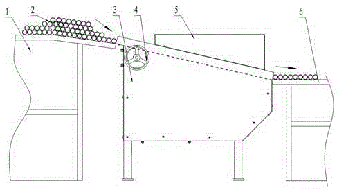
[0020] see figure 1 , the present invention includes a feeding platform 1, a material receiving platform 6 and an oiler. The straight pipe product parts 2 to be oiled are stacked on the feeding table, and then enter the oiler from the feeding table, and after oiling is completed, they are sent to the receiving table to enter the next process.

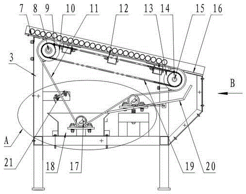
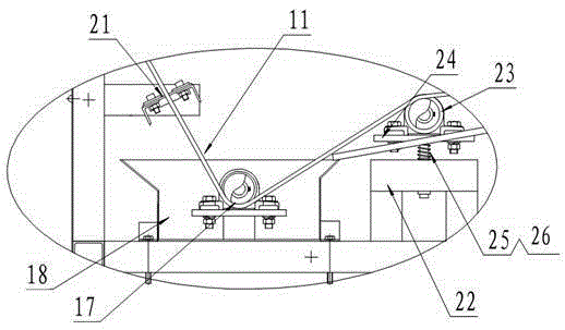
[0021] Oiler is the core technology of the present invention, see figure 2 , Figure 4 , the oiling machine is provided with an oiling rack 3, the upper part of the oiling rack is arranged obliquely, and the high end of the oiling rack is provided with a driving shaft 8, the driving shaft is connected with the hand wheel 4, and the driving shaft is equipped with a driving sprocket 9 and a driving roller 10. A driven shaft 15 is provided at the lower end of the oiling frame, and a driven sprocket 14 and a driven roller 13 are mounted on the driven shaft, and the driving sprocket and the driven wheel are connected through a chain 19 tr...


PUM

PropertyMeasurementUnit
Slopeaaaaaaaaaa

Abstract

Disclosed is a straight pipe product member oiling device. The straight pipe product member oiling device comprises a feeding table, a receiving table and an oiling machine. The oiling machine is provided with an oiling rack; the upper portion of the oiling rack is inclined; a driving shaft is disposed at the high-position end of the oiling rack and connected with a hand wheel; a driving chain wheel and a driving roller are disposed on the driving shaft; a driven shaft is disposed at the low-position end of the oiling rack; a driven chain wheel and a driven roller are disposed on the driven shaft; the driving chain wheel is in driving joint with the driven wheel through a chain; the oiling rack is provided with an oil pool; a supporting roller is disposed in the oil pool; an annular oiling felt band is arranged on the outer sides of the driving roller, the driven roller and the supporting roller in a sleeving mode; the part, located between the driving roller and the driven roller, of the oiling felt band is an inclined oiling working section which makes contact with a straight pipe product member; the width of the oiling felt band is matched with the length of the machined straight pipe product member. The straight pipe product member oiling device is novel in conception and does not need driving power during usage, and the oiling amount is easy to adjust. By means of the straight pipe product member oiling device, the product member can be uniformly oiled without drips, the labor intensity of manual work can be relieved, and the work efficiency is improved.

Description

technical field [0001] The invention relates to an oiling device for product parts, in particular to a product part oiling device for straight tubes with circular cross-sections. Background technique [0002] There is a straight pipe product with a circular cross-section in the car door. The production line process of the straight pipe product made of steel includes oiling and anti-rust treatment on the surface of the processed and inspected product. Based on the assembly requirements of the straight pipe product, the oiling process requires the surface of the straight pipe product to be evenly oiled without dripping, and it is necessary to ensure that there are oil stains within 100mm from the end of the inner hole on both sides of the straight pipe product. In order to meet the oiling requirements of the straight pipe products, the existing oiling methods are as follows: 1. Put the steel pipe products in one layer manually, use an oil spray pot to spray a layer of oil, and...

Claims


Application Information

Patent Timeline
IPC IPC(8): B05C1/06B05C11/10
Inventor 孟清水李强宋敏郭军平赵霄杨
Owner HEBEI LINGYUN ELECTROMECHANICAL
Learn More