A device for controlling tension
A tension and moving plate technology, used in manufacturing tools, metal processing, metal processing equipment, etc., can solve the problems of inability to accurately control tension and low forming accuracy of bending parts, and achieve simple structure, strong versatility and good economic benefits. Effect
- Summary
- Abstract
- Description
- Claims
- Application Information
AI Technical Summary
Problems solved by technology
Method used
Image

Examples
Embodiment 1
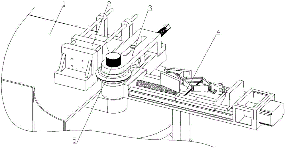
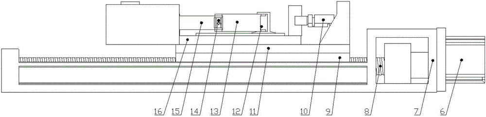
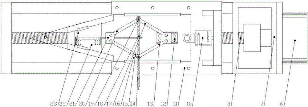
[0025] Such as Figures 1 to 3 As shown, the device for controlling tension includes a servo motor 6, a PLC, a linear module bracket 7, a ball screw 8, and a module slider 9, a sensor 10, a moving plate support 11, and a four-bar mechanism Fixed support 12, rod I13, screw pin I14, rod II15, moving plate 16, rod III17, screw 18, screw pin II19, rod IV20, four-bar mechanism mobile support 21, left clamping block 22, right clamping block 23 The clamping mechanism, the motor 6 and the sensor 10 are connected to the PLC, and the PLC controls the rotation of the servo motor 6, and the motor 6 drives the ball screw 8 to rotate, thereby driving the module slider 9 to perform linear motion, thereby causing the clamping mechanism to perform linear motion;
[0026] In the linear module, the linear module support 7 is connected to the bending machine, and the linear module support 7 is divided into a plate frame body and a frame with a raised tail. One end of the plate frame body is conne...
Embodiment 2
[0030] Such as Figures 1 to 3 As shown, the device for controlling tension includes a servo motor 6, a PLC, a linear module bracket 7, a ball screw 8, and a module slider 9, a sensor 10, a moving plate support 11, and a four-bar mechanism Fixed support 12, rod I13, screw pin I14, rod II15, moving plate 16, rod III17, screw 18, screw pin II19, rod IV20, four-bar mechanism mobile support 21, left clamping block 22, right clamping block 23 The clamping mechanism, the motor 6 and the sensor 10 are connected to the PLC, the PLC controls the rotation of the servo motor 6, and the motor 6 drives the ball screw 8 to rotate, thereby driving the module slider 9 to perform a linear motion, thereby causing the clamping mechanism to perform a linear motion;
[0031] In the linear module, the linear module support 7 is connected to the bending machine, and the linear module support 7 is divided into a plate frame body and a frame with a raised tail, one end of the plate frame body is conne...
Embodiment 3
[0035] Such as Figures 1 to 3 As shown, the device for controlling tension includes a servo motor 6, a PLC, a linear module bracket 7, a ball screw 8, and a module slider 9, a sensor 10, a moving plate support 11, and a four-bar mechanism Fixed support 12, rod I13, screw pin I14, rod II15, moving plate 16, rod III17, screw 18, screw pin II19, rod IV20, four-bar mechanism mobile support 21, left clamping block 22, right clamping block 23 The clamping mechanism, the motor 6 and the sensor 10 are connected to the PLC, the PLC controls the rotation of the servo motor 6, and the motor 6 drives the ball screw 8 to rotate, thereby driving the module slider 9 to perform a linear motion, thereby causing the clamping mechanism to perform a linear motion;
[0036] In the linear module, the linear module support 7 is connected to the bending machine, and the linear module support 7 is divided into a plate frame body and a frame with a raised tail, one end of the plate frame body is conne...
PUM
 Abstract
Description
Claims
Application Information
 - R&D
- Intellectual Property
- Life Sciences
- Materials
- Tech Scout
- Unparalleled Data Quality
- Higher Quality Content
- 60% Fewer Hallucinations
Browse by: Latest US Patents, China's latest patents, Technical Efficacy Thesaurus, Application Domain, Technology Topic, Popular Technical Reports.
© 2025 PatSnap. All rights reserved.Legal|Privacy policy|Modern Slavery Act Transparency Statement|Sitemap|About US| Contact US: help@patsnap.com