
A fixture for milling of thin-walled frame parts

A kind of milling processing and frame-like technology, which is applied in the direction of manufacturing tools, metal processing equipment, metal processing machinery parts, etc., can solve problems such as fixture deformation, and achieve the effects of preventing air leakage, good deformation prevention, and low cost

Inactive Publication Date: 2017-12-15
CENTRAL SOUTH UNIVERSITY OF FORESTRY AND TECHNOLOGY
View PDF3 Cites 0 Cited by
  • Summary
  • Abstract
  • Description
  • Claims
  • Application Information

AI Technical Summary

Problems solved by technology

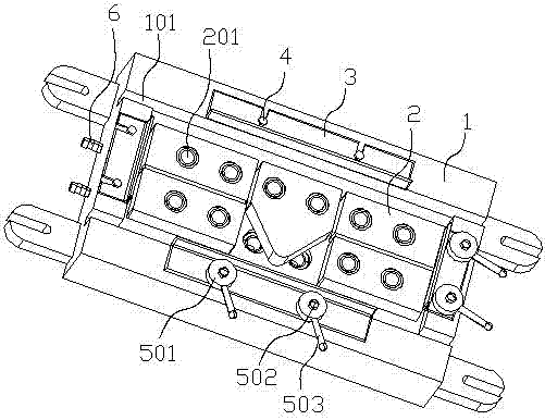
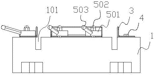
[0012] The object of the present invention is to provide a fixture for milling of thin-walled frame parts, which replaces the existing vise workbench with an adsorption workbench, so that the thin-walled frame parts can be evenly stressed during the clamping process. Then it solves the problem that the thin-walled frame parts are deformed by the fixture during milling

Method used


Image

  • A fixture for milling of thin-walled frame parts
  • A fixture for milling of thin-walled frame parts
  • A fixture for milling of thin-walled frame parts

Examples


Embodiment

[0050] Milling the 500 (length) × 230 (width) × 50 (thickness) mm rough, it is required to process double-sided thin-walled frame parts, the processing method is as follows:

[0051] The first step is to install the fixture on the milling machine and connect the pipeline of the vacuum pump; install the sealing ring in the air hole 102 and the sealing groove 202 of the movable block 2, and then insert the lower end of the corresponding movable block 2 into the upper end of the fixture. Finally, if there is The channel that is not installed with a loose block is sealed with a cover;

[0052] The second step is to place the blank on the movable block 2, pull the adjustment handle 503, and then push the movable baffle through the adjustment cam 501, and then clamp the blank;

[0053] The third step is to turn on the vacuum pump for milling;

[0054] The fourth step, after the milling process is completed, turn off the vacuum pump, loosen the positioning device 5, remove the parts...


PUM


Abstract

The invention relates to the field of clamps for thin-wall-frame-class parts, in particular to a clamp used for milling thin-wall-frame-class parts. The clamp comprises a body. A groove is formed in the center of the body. Baffles are arranged on the periphery of the groove and include the two adjacent fixed baffles fixed to the body through fixing bolts and the two adjacent movable baffles installed on the body through position adjusting devices. Air holes are evenly formed in the bottom face of the groove and communicated with an air pipe formed in the body, and the air pipe is communicated with a vacuum pump connector arranged on the outer side of the body. Movable blocks are arranged in the groove and provided with matched holes communicated with the air holes. According to the clamp used for milling thin-wall-frame-class parts, an existing jaw vice working table is replaced with a sucking working table, thin-wall-frame-class parts can be evenly stressed in the clamping process, and then the problem that thin-wall-frame-class parts are deformed by a clamp during milling is solved.

Description

technical field [0001] The invention relates to the field of fixtures for thin-walled frame parts, in particular to a fixture for milling processing of thin-walled frame parts. Background technique [0002] With the advancement of technology and economy, the use of thin-walled frame parts is becoming more and more extensive. The aviation field and other related industries will use aluminum alloy thin-walled frame parts, but the deformation of thin-walled frame parts will affect the quality during processing. It is an existing technical problem. [0003] At present, when milling thin-walled frame parts, vise workbench is generally used for clamping. Since the prominent feature of thin-walled frame parts is that the wall thickness is about 2mm, and the size of the middle partition is about 6mm, so this This method of positioning and clamping has relatively large defects; first, because the clamping part is too long and the clamping force is too large, it is easy to cause unev...

Claims


Application Information

Patent Timeline
Patent Type & Authority Patents(China)
IPC IPC(8): B23Q3/08B23Q11/00
CPCB23Q3/065B23Q3/088B23Q11/0042
Inventor 廖凯李立君尹万武薛连峰杨政杜攀吕佩琪
Owner CENTRAL SOUTH UNIVERSITY OF FORESTRY AND TECHNOLOGY
Learn More