Upper-grade structure of vacuum extruder

A high-level, vacuum technology, applied in ceramic molding machines, ceramic extrusion dies, supply devices, etc., can solve the problems of hindering the mixing and extrusion of mud materials, small extrusion force, and easy formation of dead mud areas. The effect of increased pressure and good compactness

Inactive Publication Date: 2016-03-16
CHONGQING BISHAN HONGBO TECH CO LTD
View PDF0 Cites 0 Cited by
  • Summary
  • Abstract
  • Description
  • Claims
  • Application Information

AI Technical Summary

Problems solved by technology

[0003] For the existing two-stage vacuum extruder, its upper stage usually includes an extrusion tank, an extrusion shaft, a mixing knife and a spiral reamer installed on the stirring shaft, and the upper stage is often used for preliminary mixing and extrusion of the mud. And the extrusion groove of the existing upper part is usually called cylindrical or flat-bottomed. For the cylindrical extrusion groove, the extrusion force of the mud in the extrusion groove and the wall of the cylinder is small ; For flat-bottomed extrusion grooves, during the extrusion process, dead mud areas are easily formed in the extrusion grooves, which hinder the mixing and extrusion of mud materials

Method used


Image

  • Upper-grade structure of vacuum extruder
  • Upper-grade structure of vacuum extruder
  • Upper-grade structure of vacuum extruder

Examples


Embodiment 1

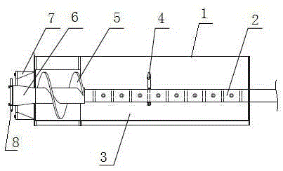
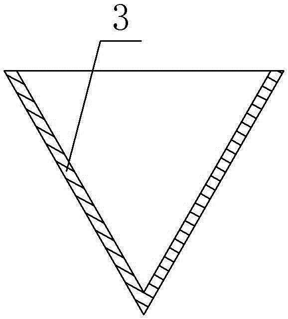
[0020] Embodiment 1 is basically as attached figure 1 and image 3 As shown, a superstructure of a vacuum extruder includes an extrusion cylinder 1, an extrusion shaft 2, a stirring knife 4 and a spiral reamer 5 installed on the extrusion shaft 2, and the extrusion cylinder 1 is equipped with a feed mouth, this embodiment also includes a V-shaped extrusion groove 3 located in the extrusion cylinder 1, the extrusion shaft 2 is connected to the slot of the extrusion groove 3 through bearing rotation, and the extrusion shaft 2 is close to the inlet A number of mixing knives 4 are installed on one side of the feed port, and a spiral reamer 5 is welded on the side of the extrusion shaft 2 away from the feed port.

[0021] In this embodiment, the mixing knives 4 are distributed in a spiral on the extrusion shaft 2 , the angle formed between two adjacent mixing knives 4 is 90°, and the mixing knives 4 are connected to the extrusion shaft 2 by bolts. . The mixing knife 4 forming a ...

Embodiment 2

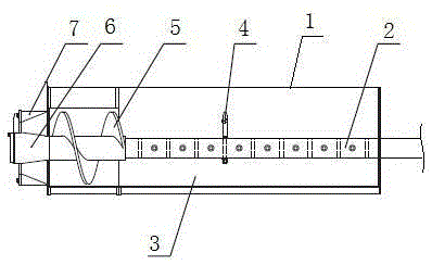
[0024] Such as figure 2 As shown, the difference from Embodiment 1 is that: the end of the extrusion shaft 2 away from the feed inlet is connected with a disc-shaped slime cutting disc 8 . The disc-shaped mud cutting cutter head 8 rotates together with the extruding shaft 2, and when the mud material is extruded, it can be broken into pieces by the disc-shaped mud cutting cutter head 8, so that the air in the mud material can be discharged.

[0025] Specific workflow:

[0026] Take embodiment 1 as an example to describe in detail below: figure 1 As shown, in specific use, start the vacuum extruder, the extrusion shaft 2 rotates, and then add the mud to be processed from the feed port, and the extrusion shaft 2 drives the stirring knife 4 and the spiral reamer 5 to rotate during the rotation process. The mixing knife 4 stirs the mud in the extrusion groove 3. Since the extrusion groove 3 is V-shaped, the mud is squeezed with the side wall of the extrusion groove 3 when being...


PUM


Abstract

The invention discloses an upper-grade structure of a vacuum extruder. The upper-grade structure comprises an extrusion barrel, an extrusion shaft, stirring cutters and a spiral reamer, wherein the stirring cutters and the spiral reamer are installed on the extrusion shaft; a feeding opening is formed in the extrusion barrel; the upper-grade structure further comprises a V-shaped extrusion groove located in the extrusion barrel, the extrusion shaft is connected into a groove opening of the extrusion groove in a rotational manner, the multiple stirring cutters are installed on one side, close to the feeding opening, of the extrusion shaft, and the spiral reamer is connected to one side, far away from the feeding opening, of the extrusion shaft. By means of the upper-grade structure of the vacuum extruder, the extrusion action force of mud and the inner wall of the extrusion groove can be large, a dead mud zone cannot be formed, and extrusion of the mud is facilitated.

Description

technical field [0001] The invention belongs to the field of materials being extruded in a press, and in particular relates to a superstructure of a vacuum extruder. Background technique [0002] The vacuum extruder adopts the principle of single extrusion, single shaft, single mud cylinder, single screw coaxial sealing mechanism. The body is all welded by steel plate. Reasonable structural design, high extrusion pressure. Suitable for shale, high-volume fly ash, coal gangue, clay and other raw materials to produce hollow bricks of various specifications. This machine has strong practicability, small investment and quick effect, and is an ideal equipment for technical transformation of brick factories. The vacuum extruder is used to stir the mud, vacuumize it, and screw out the mud sticks that meet the requirements. The types of vacuum extruders can be divided into single-stage and double-stage. Two-stage vacuum extruders are divided into upper part and lower part. The u...

Claims


Application Information

Patent Timeline
Patent Type & Authority Applications(China)
IPC IPC(8): B28B3/22B28B3/26B28B13/02B28B11/16
CPCB28B3/22B28B3/26B28B11/16B28B13/0235
Inventor 曹杨
Owner CHONGQING BISHAN HONGBO TECH CO LTD
Why Eureka
Try Eureka