Catheter and method of manufacturing catheter

Inactive Publication Date: 2011-12-01
SUMITOMO BAKELITE CO LTD
View PDF3 Cites 20 Cited by
  • Summary
  • Abstract
  • Description
  • Claims
  • Application Information

AI Technical Summary

Benefits of technology

[0019]According to the catheter of the present invention, since the second resin material having the largest hardness is configured to increase the thickness from the distal end side towards the proximal end side

Problems solved by technology

In such recent catheters, represented by the catheter disclosed in Patent Document 1, having the flexibility stepwisely varied over a plurality of sections aligned in the longitudinal direction thereof, it may be difficult to ensure subtle manipulation through the operating wire.
For this reason, relation of the length of pushing or pulling of the operating wire, with the amount of flexion of the distal end may be complicated, and it may therefore become difficult to

Method used


Image

  • Catheter and method of manufacturing catheter
  • Catheter and method of manufacturing catheter
  • Catheter and method of manufacturing catheter

Examples


modified example

[0155]FIG. 7 is a partial schematic vertical sectional view illustrating the catheter 10 of a modified example. The drawing illustrates a cross section of the end portion of the catheter 10 cut in the longitudinal direction.

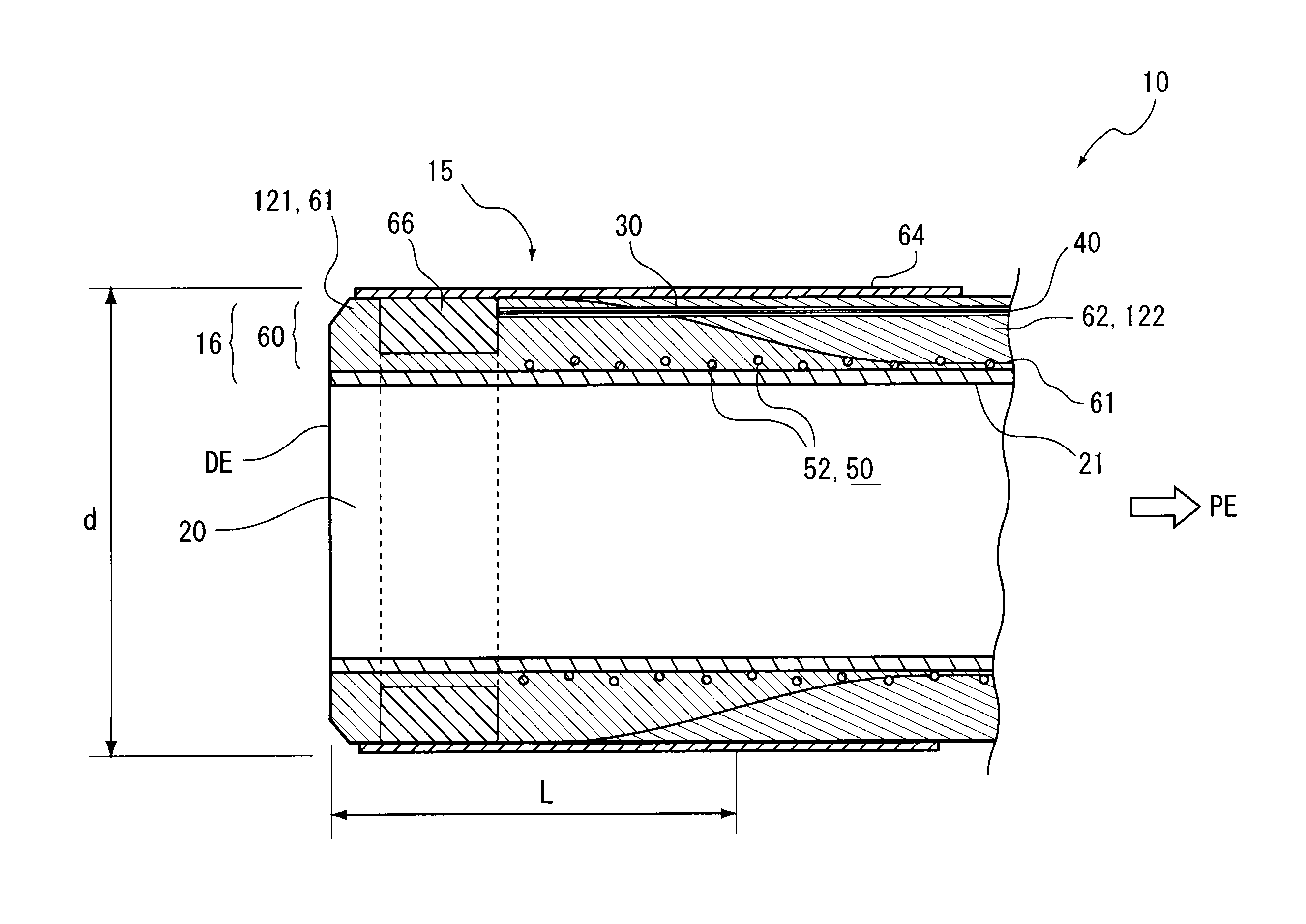
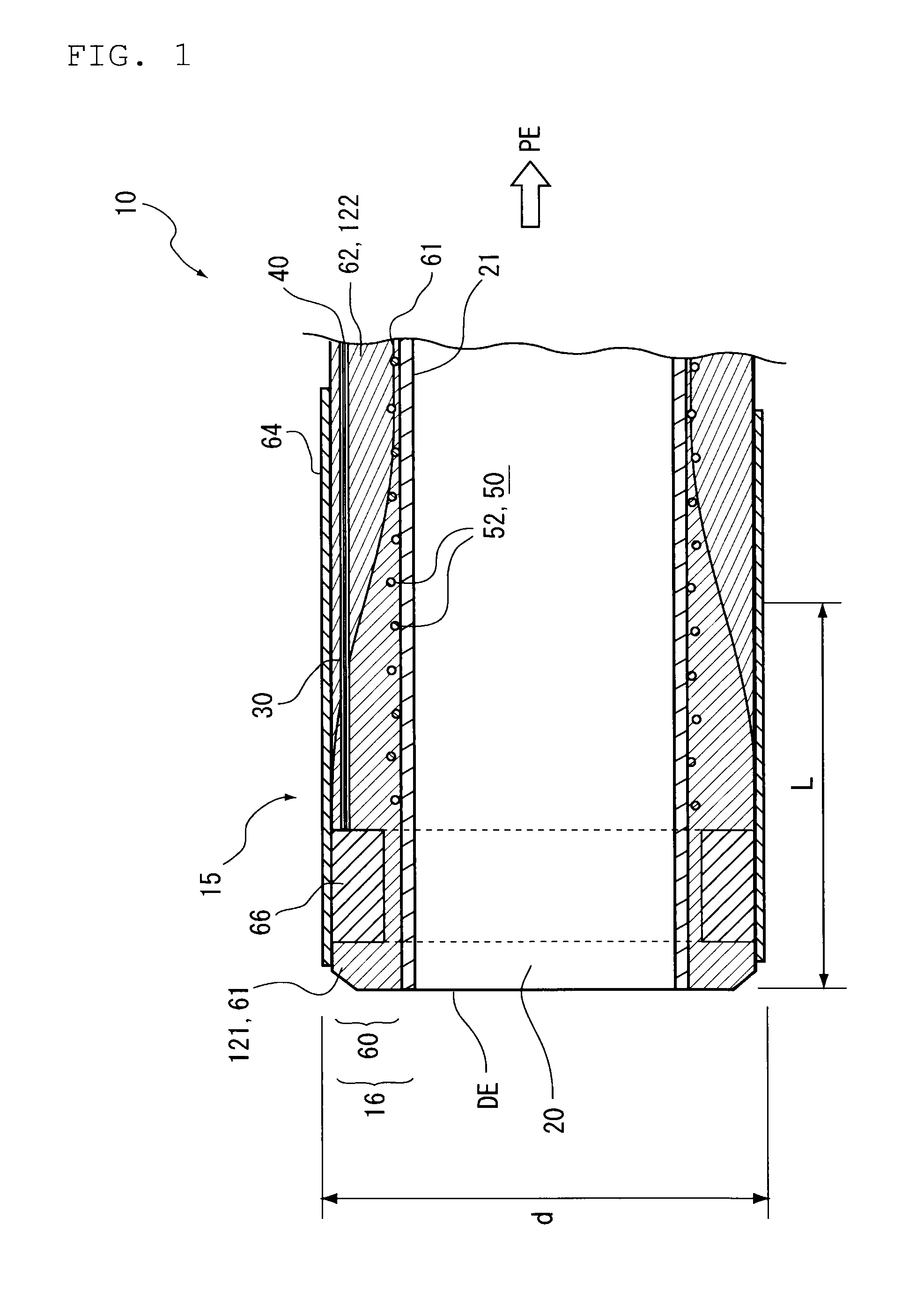
[0156]In this modified example, the first resin layer 61 is provided on the outer circumferential side of the second resin layer 62, over a partial length of the sheath 16 on the distal end DE side thereof.

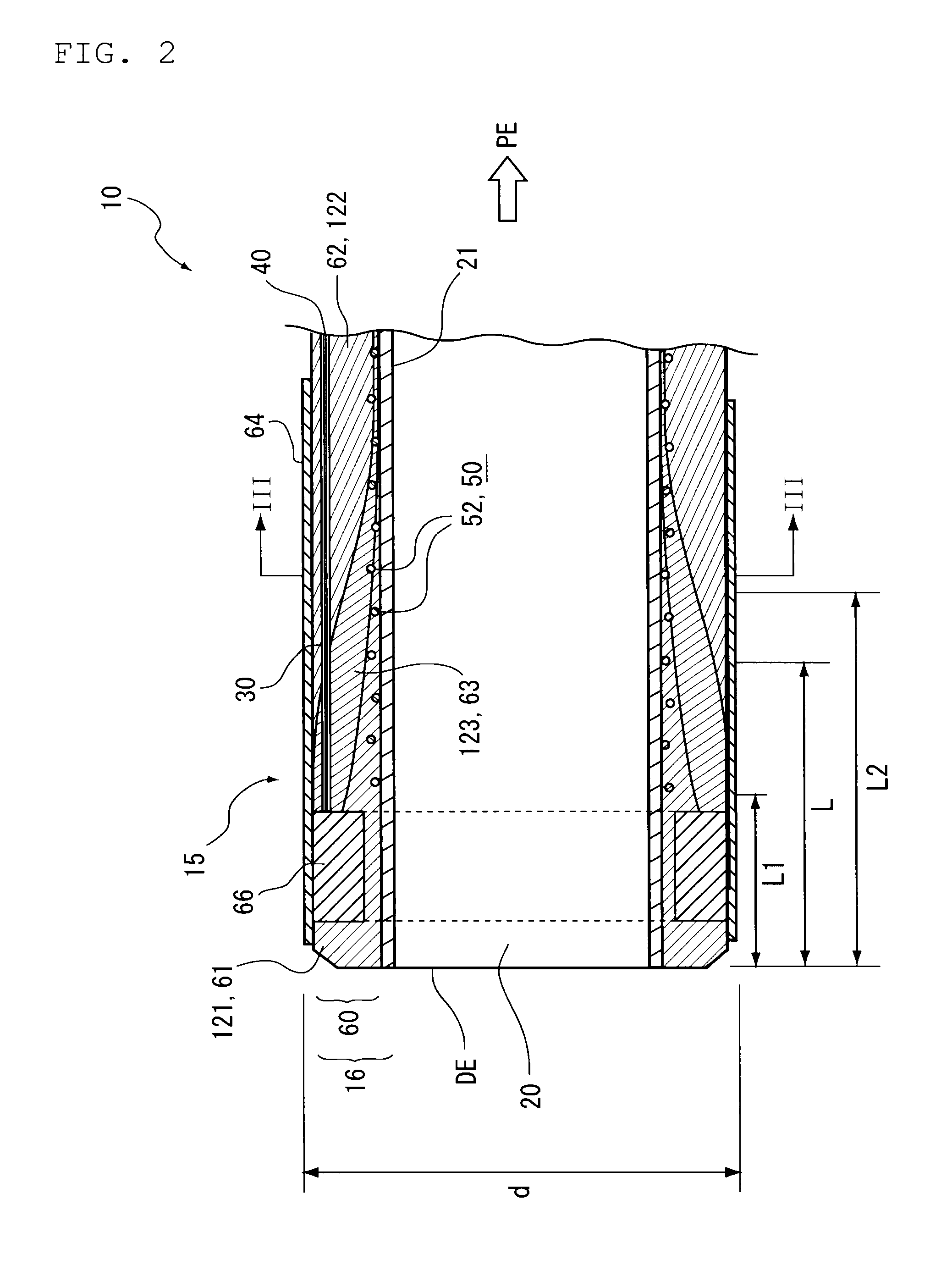
[0157]In the catheter 10 of this modified example, the second resin layer 62 is formed on the inner side of the first resin layer 61. More specifically, the first resin layer 61, the third resin layer 63 and the second resin layer 62 are stacked in this order when viewed from the outer circumferential side, so as to form the outer layer 60.

[0158]The second resin layer 62 has a uniform thickness in the vicinity of the distal end DE of the sheath 16, and gradually increases beyond a middle point of the length of the distal end section 15.

[0159]The thickness of th...


PUM

PropertyMeasurementUnit
Thicknessaaaaaaaaaa
Diameteraaaaaaaaaa
Lengthaaaaaaaaaa

Abstract

A main lumen (20) and sub-lumens (30) having a diameter smaller than that of the main lumen (20) are respectively formed in a sheath (16) of a catheter (10) in the longitudinal direction thereof so as to extend therethrough. An operating wire (40) is laid through each sub-lumen (30) in a slidable manner, with the end thereof fixed to the distal end section (15) of the sheath (16). The sheath (16) is configured a first resin layer (61) and a second resin layer (62) having a hardness higher than that of the first resin layer (61), stacked in the thickness-wise direction, each of which being composed of a resin material. In the sheath (16), the thickness of the second resin layer (62) increases from the distal end side towards the proximal end side.

Description

TECHNICAL FIELD[0001]The present invention relates to a catheter, and a method of manufacturing a catheter.BACKGROUND ART[0002]Recently, there has been proposed a catheter, the direction of insertion of which into a body cavity is controllable by allowing the distal end section thereof to bend. As one mode of bending of the distal end of the catheter, a known catheter is configured to operate a wire fixed to the distal end, at the proximal end side (see Patent Document 1 below).[0003]The wire (operating wire) laid through a lumen of the body of the catheter (tubular body) has a predetermined rigidity, and the distal end of the tubular body is bent by pushing the wire. The tubular body herein is sectioned in the longitudinal direction into about four or five sections aligned in series, having stepwisely different flexibility, wherein the rigidity increases towards the proximal end side, and conversely the flexibility increases towards the distal end side. According to the description...

Claims


Application Information

Patent Timeline
IPC IPC(8): A61M25/00D01D5/24B29C48/09
CPCA61B1/0011A61L29/085A61M25/0009A61M25/0012A61M25/0045A61M25/005B29L2031/7542A61M25/0108B29C47/0023B29C47/025B29C47/065B29C47/265B29C47/28A61M25/0054B29C48/09B29C48/154B29C48/21B29C48/3366B29C48/34A61M25/01A61M25/00
Inventor TANAKA, HAYAOHAYASHI, HIROYUKI
Owner SUMITOMO BAKELITE CO LTD
Why Eureka
Try Eureka