Carbon dioxide phase change coal seam fracturing device and utilization method
A carbon dioxide and cracker technology, applied in outburst prevention technology and device, anti-reflection, coal body cracking field, can solve problems such as many failures, low efficiency, cable disconnection, etc., to achieve high reliability and facilitate powder discharge , the effect of high work efficiency
- Summary
- Abstract
- Description
- Claims
- Application Information
AI Technical Summary
Problems solved by technology
Method used
Image

Examples
Embodiment 1
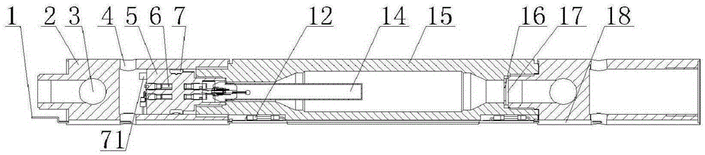
[0023] see figure 1 , figure 2 , a carbon dioxide phase-change coal seam cracker, including a cylinder body 15 threadedly connected to a valve body 5, characterized in that: both ends of the cylinder body 15 are threadedly connected to a connector 2 with an explosion vent hole 3, and the connector 2 has a cable routing The hole 4, the cylinder body 15 and the two connectors 2 are provided with a cable slot 18 for placing the cable 1.
[0024] Among them: one end of the cylinder body 15 is placed in contact with a connector 2 with a shear piece 17, the valve body 5 has a terminal post 6, a filling port 7, and a filling switch 71, and the valve body 5 also has a valve body placed on the cylinder body 15. Inside the heating device 14, a copper gasket 16 is also placed at the contact part between one end of the cylinder body 15 and a connector 2.
Embodiment 2
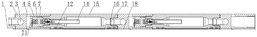
[0026] see figure 1 , figure 2 , a carbon dioxide phase-change coal seam cracker, including a cylinder body 15 threadedly connected to a valve body 5, characterized in that: both ends of the cylinder body 15 are threadedly connected to a connector 2 with an explosion vent hole 3, and the connector 2 has a cable routing The hole 4, the cylinder body 15 and the two connectors 2 are provided with a cable slot 18 for placing the cable 1.
[0027] Among them: one end of the cylinder body 15 is placed in contact with a connector 2 with a shear piece 17, the valve body 5 has a terminal post 6, a filling port 7, and a filling switch 71, and the valve body 5 also has a valve body placed on the cylinder body 15. Inside the heating device 14, a copper gasket 16 is also placed at the contact part between one end of the cylinder body 15 and a connector 2.
[0028] Wherein: the cable slot 18 where the cable 1 is placed is blocked with a resin material, and the wire slots 18 at both ends...
Embodiment 3
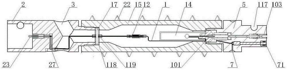
[0031] see image 3 , Figure 4 , Figure 5 , a carbon dioxide phase change coal seam cracker, comprising a cylinder body 15 with one end screwed to a valve body 5, the other end of the cylinder body 15 to be screwed to a connector 2, the valve body 5 with a filling port 7, a filling switch 71, placed on The heating device in the cylinder body 15 is characterized in that: the valve body 5 also has a connecting pin hole 117, an electrode upper end 103 of one cable line 1, an electrode terminal 101 using the cylinder body 15 as another cable line, and the connecting head 2 has a There are connecting pin holes 117, the electrode lower end 23 of the cable 1, the cable connecting terminal 27, the explosion venting hole 3, and the metal shearing piece 17 connecting the cable 1 is provided at the contact part of the cylinder 15 threadedly connected to the connector 2.
[0032] Wherein: the metal shearing piece 17 uses the sealing insulating sleeve 118 as a sealing gasket, and the t...
PUM
 Abstract
Description
Claims
Application Information
PatSnap Eureka turns technology decisions into work you can execute. Powered by our Innovation Knowledge Graph, it runs expert workflows across engineering, life sciences, materials and intellectual property. Get your review-ready output in minutes.


