
Power output system and output method for agricultural machinery

A technology for power output and agricultural machinery, which is applied in mechanical equipment, transmission devices, fluid transmission devices, etc., can solve the problems of high working pressure, limited engine speed, and high cost of high pressure in the walking hydraulic system, so as to reduce working pressure and increase input Speed, the effect of increasing the output speed

Active Publication Date: 2016-03-16
LUOYANG INST OF SCI & TECH
View PDF6 Cites 2 Cited by
  • Summary
  • Abstract
  • Description
  • Claims
  • Application Information

AI Technical Summary

Problems solved by technology

[0002] The walking system of agricultural machinery needs a lot of power, especially for large and medium-sized harvesting machinery. The weight of the vehicle is relatively large, and the power required for walking is relatively large. When using a hydraulic system to transmit power, it is difficult to increase the power of the hydraulic system. 2200-2400r / min, the engine speed is limited, so the method of increasing the working pressure of the system is used to increase the power of the hydraulic system, resulting in the high pressure and high cost of the walking hydraulic system
At present, the power output used by agricultural machinery is to reduce the engine speed first, and then distribute it, resulting in higher and higher working pressure of the walking hydraulic system; in addition, the increase of the driving torque of the walking is closely related to the output torque of the hydraulic system, and the improvement of the driving torque of the walking At present, it is usually obtained by increasing the output torque of the hydraulic system, and increasing the output torque of the hydraulic system is achieved by increasing the working pressure, which intensifies the increase in the working pressure of the hydraulic system, and tends to develop towards ultra-high pressure, resulting in a significant increase in system costs. Increase

Method used


Image

  • Power output system and output method for agricultural machinery

Examples


Embodiment Construction

[0018] The present invention will be further elaborated below in combination with specific embodiments.

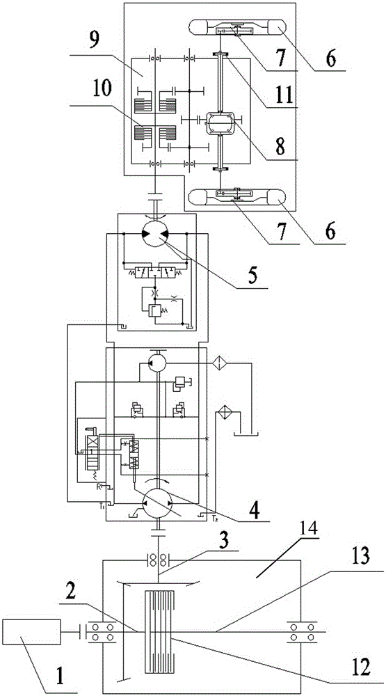
[0019] As shown in the figure: a power output system for agricultural machinery, the system includes an engine 1, a power output mechanism 14 and a walking system, the engine 1 outputs power to the walking system and the working system through the power output mechanism 14, and the power output mechanism 14 Including power input shaft 2, bevel gear, main clutch 12, walking system power output shaft 3 and working system power output shaft 13, power output mechanism 14 outputs power to the working system through the main clutch 12, and at the same time outputs power to the walking system through bevel gear transmission system, the main clutch 12 and the bevel gear transmission are included in the power take-off mechanism 14 housings, the power output shaft 13 of the working system and the power output shaft 3 of the walking system are all output through the 14 housings of the...


PUM


Abstract

The invention relates to a power output system and output method for agricultural machinery. The system comprises an engine, a power output mechanism and a walking system, wherein the engine outputs power to the walking system and a working system through the power output mechanism. A wet clutch is adopted, the control model can be mechanical clutch, hydraulic clutch and pneumatic clutch, and the operation is labor-saving. Hub reduction can adopt internal-meshing open gear transmission or external-meshing close gear transmission. A speed changing box is a two-gear box, so that the structure is simple and the operation is convenient. The power output method increases the input speed of a hydraulic pump, increases the power of a hydraulic system, increases the output speed of a hydraulic motor, reduces the working pressure of the hydraulic system, and reduces the cost of the system.

Description

technical field [0001] The invention relates to the field of agricultural machinery, in particular to a power output system and output method for agricultural machinery. Background technique [0002] The walking system of agricultural machinery needs a lot of power, especially for large and medium-sized harvesting machinery. The weight of the vehicle is relatively large, and the power required for walking is relatively large. When using a hydraulic system to transmit power, it is difficult to increase the power of the hydraulic system. 2200-2400r / min, the engine speed is limited, so the method of increasing the working pressure of the system is used to increase the power of the hydraulic system, resulting in the high pressure and high cost of the walking hydraulic system. At present, the power output used by agricultural machinery is to reduce the engine speed first, and then distribute it, resulting in higher and higher working pressure of the walking hydraulic system; in a...

Claims


Application Information

Patent Timeline
IPC IPC(8): F16H47/02
CPCF16H47/02
Inventor 卢文涛张春伟王荣先温广宇刘明国邓志刚
Owner LUOYANG INST OF SCI & TECH
Learn More