Burner, combustor and gas stove

A burner and burner technology, applied in the direction of burners, gas fuel burners, combustion methods, etc., can solve the problems of low combustion efficiency, high smoke emission, gas flow obstruction, etc., to improve the ejection effect, reduce Effects of flue gas emission and improvement of combustion efficiency

Inactive Publication Date: 2016-03-16
GUANGDONG HISENSE HOME APPLIANCES CO LTD
View PDF6 Cites 7 Cited by
  • Summary
  • Abstract
  • Description
  • Claims
  • Application Information

AI Technical Summary

Problems solved by technology

[0003] Since the sub-mixing chamber is located inside the main mixing chamber, and both the main injection tube and the sub-extracting tube are located outside the main mixing chamber, there must be a junction between each injection tube and its corresponding mixing chamber. In the existing technology, due to the unreasonable design of the burner head, the intersection will interfere and form a bulge, and the bulge will hinder the flow of gas and affect the injection, resulting in low injection efficiency and low combustion efficiency. Combustion defects such as high flue gas emission

Method used


Image

  • Burner, combustor and gas stove
  • Burner, combustor and gas stove
  • Burner, combustor and gas stove

Examples


Embodiment Construction

[0020] The specific implementation manners of the present invention will be further described in detail below in conjunction with the accompanying drawings.

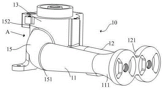
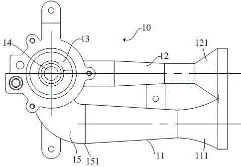
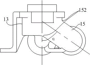
[0021] refer to Figure 1 to Figure 5 , a furnace head 10, including a main injection tube 11, a secondary injection tube 12, a main mixing chamber 13 connected to and communicated with the main injection tube 11, and a secondary mixing chamber connected to and communicated with the secondary injection tube 12 14. The auxiliary mixing chamber 14 is located inside the main mixing chamber 13 and coaxially arranged with the main mixing chamber 13, that is, the two are concentrically sleeved, and the main ejector pipe 11 and the auxiliary ejector pipe 12 are both located in the main mixing chamber Outside the body 13, the main injection tube 11 is located on one side of the auxiliary injection tube 12. The structure, positional relationship and effect of the above-mentioned components are the same as those of the prior art; ...


PUM


Abstract

The invention provides a burner, a combustor and a gas stove. The burner comprises a main ejection pipe, a sub ejection pipe, a main mixing cavity and a sub mixing cavity, wherein the sub mixing cavity and the main mixing cavity are coaxially arranged; the main ejection pipe and the sub ejection pipe are positioned at the outer part of the main mixing cavity; the axis of the sub ejection pipe and the axis of the sub mixing cavity are in the same plane, and the sub ejection pipe is positioned below the main mixing cavity; a main ejection transition pipe is connected between the main ejection pipe and the main mixing cavity; and the main ejection transition pipe is an oblique pipe oblique upwards from the connection end of the main ejection transition pipe and the main ejection pipe to the connection end of the main ejection transition pipe and the main mixing cavity. According to the burner, the resistance to air flow can be greatly reduced, the ejection effect is improved, the combustion efficiency is improved, and the flue gas emission is reduced; through the adoption of a combustor with the burner and a gas stove, the ejection effect can be further improved, the combustion efficiency is improved, and the glue gas is reduced.

Description

technical field [0001] The invention relates to the structural improvement of the gas stove burner, in particular to the structural improvement of the burner head. Background technique [0002] The burner is an important part of the gas stove, which determines the performance of the gas stove. Commonly used burners mainly include a burner head, an ejector pipe connected to the burner head, a gas distribution plate above the burner head, and a fire cover arranged above the gas distribution plate. Among them, the burner head is one of the important structural components of the burner. Its function is to introduce gas from the gas nozzle, inject air from the inlet of the burner head, mix air and gas into the gas distribution plate, and increase the speed and pressure of the mixed gas. As evenly as possible. The furnace head structure usually includes a main ejector tube, an auxiliary ejector tube, a main mixing chamber connected to the main ejector tube, and an auxiliary mixi...

Claims


Application Information

Patent Timeline
Patent Type & Authority Applications(China)
IPC IPC(8): F23D14/04F23D14/64
CPCF23D14/04F23D14/64
Inventor 胡杨朱鑫史振京
Owner GUANGDONG HISENSE HOME APPLIANCES CO LTD
Why Eureka
Try Eureka