Induction Capacitor Generator

A technology of inductive capacitors and generators, applied in the direction of induction generators, etc., can solve the problems of large power consumption of permanent magnet stator, electromagnet stator, etc., achieve high power generation efficiency, long service life, and avoid the effect of consuming a lot of power

Active Publication Date: 2017-12-05
李鹏卓
View PDF7 Cites 0 Cited by
  • Summary
  • Abstract
  • Description
  • Claims
  • Application Information

AI Technical Summary

Problems solved by technology

[0005] The purpose of the present invention is to provide an induction capacitor generator, which solves the technical problems of magnetization of the rotor of the electromagnetic induction generator in the prior art, demagnetization of the permanent magnet stator, and the consumption of a large amount of electric energy by the electromagnet stator based on the basic principle of "static induction and rotating capacitance".

Method used


Image

  • Induction Capacitor Generator
  • Induction Capacitor Generator
  • Induction Capacitor Generator

Examples


Embodiment 1

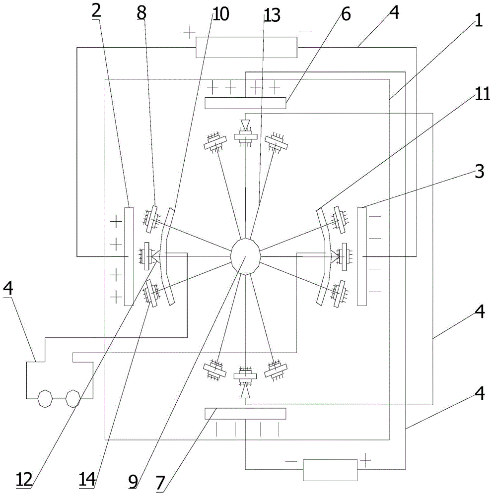
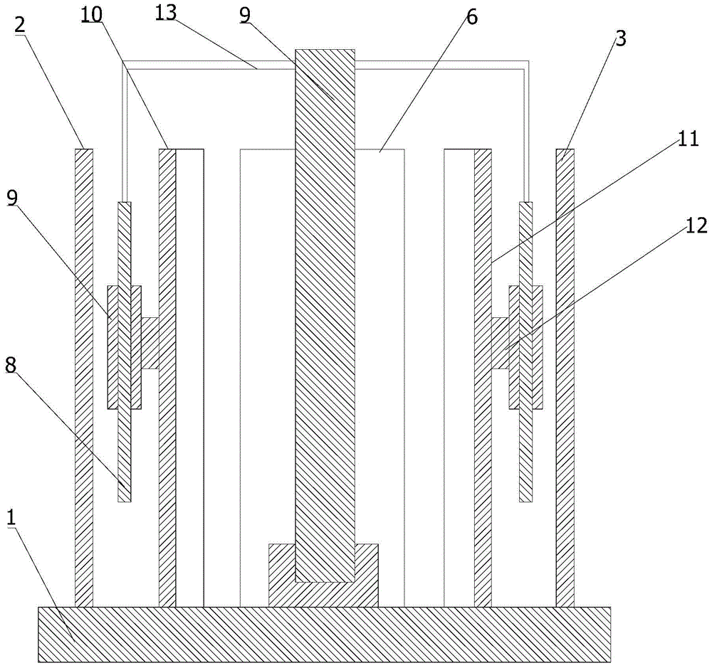
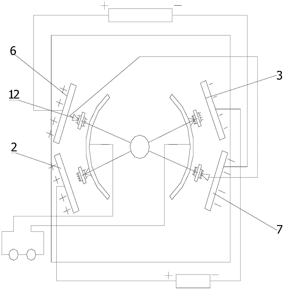
[0041] Such as Figure 1-2 As shown, an induction capacitor generator is provided in this embodiment, the induction capacitor generator includes an insulated base 1, and a first metal plate 2 and a second metal plate are vertically arranged on the base 1 3. The first metal plate 2 and the second metal plate 3 are arranged parallel to each other, the first metal plate 2 is connected to the positive pole of the DC high-voltage power supply 5 through the wire 4, and the second metal plate 3 is connected to the DC power supply through the wire 4 High voltage power supply 5 negative pole;

[0042] The base 1 is also vertically provided with a third metal plate 6 and a fourth metal plate 7, the third metal plate 6 and the fourth metal plate 7 are arranged parallel to each other, and the third metal plate 6 The positive pole of the DC high-voltage power supply 5 is connected through the wire 4, and the fourth metal plate 7 is connected with the negative pole of the DC high-voltage p...


PUM


Abstract

The invention provides an inductive capacitance generator and belongs to the generator field. The inductive capacitance generator comprises a base; a first metal plate and a second metal plate are vertically arranged on the base; the first metal plate is connected with the positive pole of a high-voltage direct-current power source through a wire; the second metal plate is connected with the negative pole of the high-voltage direct-current power source through a wire; a third metal plates and a fourth metal plate are also vertically arranged on the base; each capacitor assembly includes a rotating plate and pins; the center of the capacitor assembly is provided with a central shaft; the central shaft is rotationally connected by the base and is fixedly connected with the rotating plate through a support; a first metal induction block and a second metal induction block are fixed on the base; a metal contact block is fixed to one side of the first metal induction block which is adjacent to the first metal plate and one side of the second metal induction block which is adjacent to the second metal plate respectively; and the two metal blocks both abut against pins at inner sides. With the inductive capacitance generator adopted, technical problems such as the magnetization of the rotor, the demagnetization of the permanent magnet stator and large amount of electric energy consumption of the electromagnet stator of an electromagnetic induction generator in the prior art can be solved.

Description

technical field [0001] The invention relates to the field of generators, in particular to an induction capacitor generator. Background technique [0002] The current commonly used alternators use the principle of electromagnetic induction to make the conductor cut the magnetic induction line to generate electricity. The biggest disadvantage of this kind of generator is that not only the structure is complicated, but also its power generation efficiency will be greatly reduced as the use time is extended, because the current in the rotor itself is also generating a changing magnetic field, and the long-term existence of this magnetic field, It will cause the permanent magnet on the stator to demagnetize, resulting in lower and lower power generation efficiency. Therefore, the large-scale three-phase alternating generators currently used all use electromagnets on the stator to prevent the efficiency of the generator from decreasing due to stator demagnetization, but the elect...

Claims


Application Information

Patent Timeline
Patent Type & Authority Patents(China)
IPC IPC(8): H02N1/08
CPCH02N1/08
Inventor 李鹏卓
Owner 李鹏卓
Why Eureka
Try Eureka