Lubricator

A technology of lubricants and cylinders, which is applied in the direction of lubrication pumps, distribution devices, lubrication parts, etc., can solve the problems of increased cost, difficulty in fitting lubricants, complicated installation, etc., and achieve the effect of reducing lubrication costs

Inactive Publication Date: 2016-03-16
HANIL LUBTEC
View PDF4 Cites 1 Cited by
  • Summary
  • Abstract
  • Description
  • Claims
  • Application Information

AI Technical Summary

Problems solved by technology

However, since the dispensing valve is added to a separate pump, this technique also has problems that installation is complicated and cost is increased
However, this application has the problem that different amounts of lubricant are difficult to be supplied by this technique to two lubrication points, which require the same amount of lubricant because of the line resistance created in the respective channels

Method used


Image

  • Lubricator
  • Lubricator
  • Lubricator

Examples


Embodiment Construction

[0045] Preferred embodiments of the present invention will be described with reference to the accompanying drawings below. In the following description of the present invention, detailed descriptions of related known functions and constructions will be omitted when they would unnecessarily obscure the present invention.

[0046] (Structure of lubricating device)

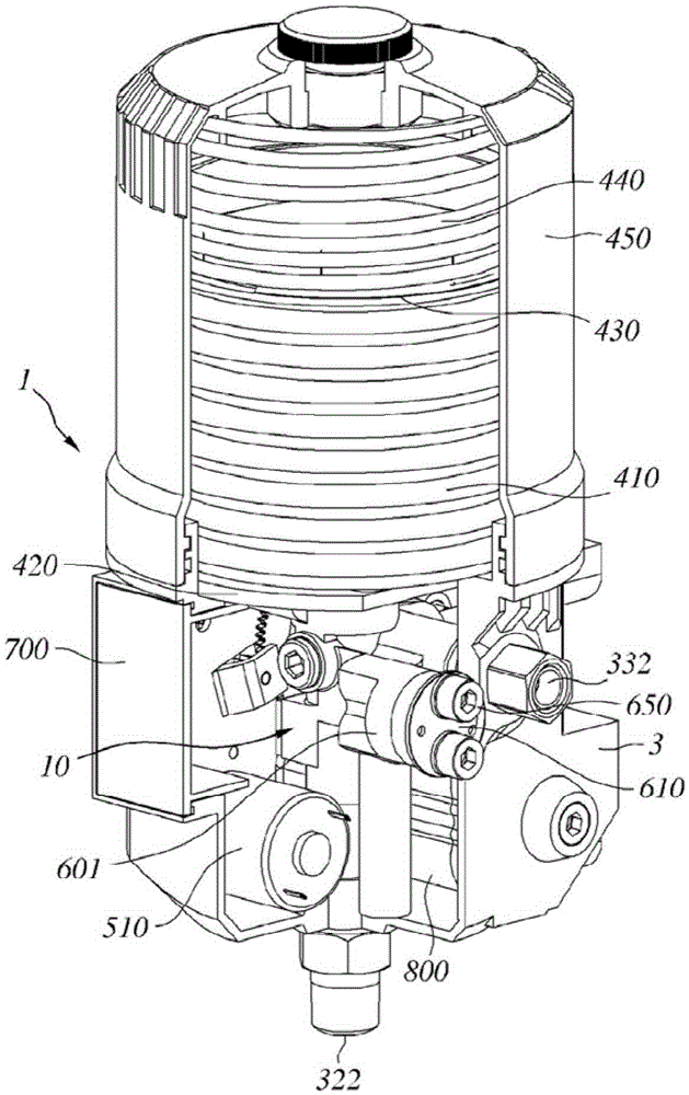
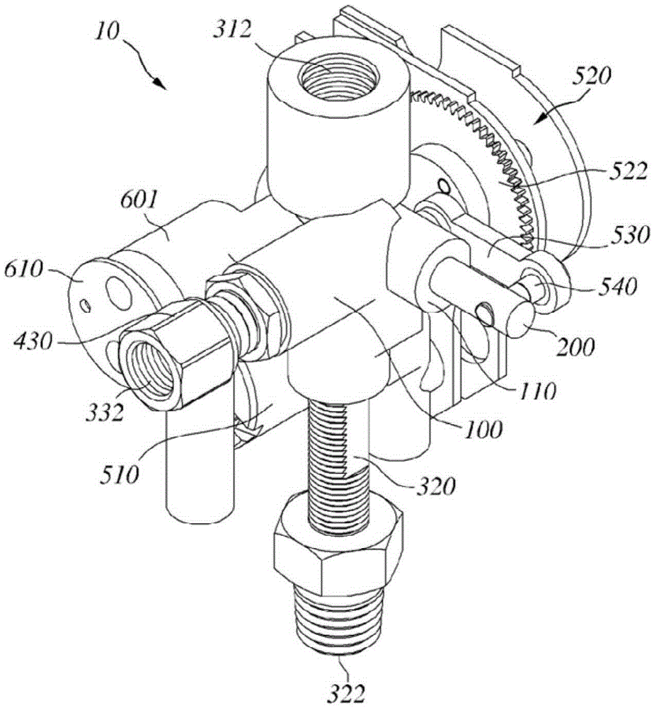
[0047] figure 2 is a partial cross-sectional schematic diagram of a lubricant adding device according to the present invention, image 3 is a schematic diagram of the pump unit of the lubricating device according to a specific embodiment of the present invention, and Figure 4 is a cross-sectional view of the lubricating device according to the present invention.

[0048] as in figure 2 Shown in, the lubricant adding device described in the specific embodiment of the present invention, in image 3 The pump unit 10 shown in is installed in the housing 3. In this example, the pump unit 10 comprises a first outl...


PUM


Abstract

The present invention relates to a lubricator capable of efficiently supplying a lubricant to two portions requiring lubrication without a separate distribution device, the lubricator comprising a pump and two outlets. To this end, provided is a lubricator comprising: a pump body; a piston; first to fourth check valves; a lubricant storage unit; and a piston driving unit. The pump body comprises: a cylinder; an inlet flow path; a first outlet flow path; and a second outlet flow path, wherein one end of the cylinder is closed and the other end of the cylinder is opened, the inlet flow path is formed in one end side of the cylinder such that the inlet flow path is vertically connected with the cylinder, the first outlet flow path is formed to be connected with the cylinder while facing the inlet flow path, the second outlet flow path is formed to be connected with the cylinder while being spaced apart by a predetermined distance in the direction of the other end of the cylinder from the position where the inlet flow path and the first outlet flow path are formed. The piston comprises an internal flow path which connects an inlet hole formed in one end of the piston and a circumference groove formed to be spaced apart from the inlet hole by a predetermined distance in the direction of the other end of the piston. The piston is adapted to be inserted into the cylinder. The first to fourth check valves are respectively positioned in the inlet side of the inlet flow path, the outlet side of the first and second outlet flow paths, and the internal flow path of the piston. The lubricant storage unit in which the lubricant is stored is connected to a first check valve. The driving unit drives the piston such that the inlet hole of the piston reciprocates between one end of the cylinder and one position of the first and second outlet flow paths.

Description

technical field [0001] The present invention generally relates to a lubricating device which includes a pump and two outlets and is capable of efficiently supplying lubricant to two lubricating target points without the need for distribution means. Background technique [0002] In general, lubrication pumps are commonly used to supply lubricant, such as grease or oil, to lubrication target points in various rotating machines, such as electric motors, pumps, and bellows. In this example, the lubrication target points simply refer to the bearings that are used to support the shafts of rotating machines. [0003] figure 1 is a diagram showing the application of a conventional lubrication pump. A traditional typical lubrication pump is a small pump with a single outlet. Therefore, the lubrication pump itself can supply lubricant to a single lubrication target point. [0004] However, typical rotating machines, such as in figure 1 The motor M shown in , has two lubrication t...

Claims


Application Information

Patent Timeline
Patent Type & Authority Applications(China)
IPC IPC(8): F16N25/02F16N23/00
CPCF16N7/36F16N13/22F16N25/02F16N23/00F16N13/06F16N13/16F16N2013/063
Inventor 金饶旎
Owner HANIL LUBTEC
Why Eureka
Try Eureka