Continuous casting and rolling production line of wire rods and production method of production line

A technology of continuous casting, continuous rolling and production methods, which is applied in the direction of metal rolling, etc., can solve the problems of low working speed of the transport roller table, low pulling speed of the continuous casting machine, and long duration, so as to reduce the construction cost and operation and maintenance. Cost, reduction of conveying time and temperature loss, effect of uniform temperature gradient distribution

Inactive Publication Date: 2016-03-23
CISDI ENG CO LTD
View PDF11 Cites 19 Cited by
  • Summary
  • Abstract
  • Description
  • Claims
  • Application Information

AI Technical Summary

Problems solved by technology

[0003] There are many problems and deficiencies in this production method: 1) The continuous casting machine has low casting speed, low output, and many streams. 4 streams to 8 streams; 2) Multi-strand slabs are collected and sent to the steel rolling workshop in sequence with complex process and long time; 3) The working speed of the transport roller table is not high, generally 0-60m / min; 4) Casting slab casting speed Low, long production process, high temperature loss, cannot guarantee that the surface temperature of the slab is greater than 900°C when it is directly hot sent to the entrance of the rolling mill
[0004] Therefore, the existing wire and bar production methods have shortcomings such as uncompact work flow, low production efficiency, high energy consumption, and poor economy. The transportation process lasts for a long time and the temperature loss is too high. It is necessary to add a slab heating furnace to meet the rolling requirement that the surface temperature of the slab at the entrance of the rolling mill is greater than 900°C.

Method used


Image

  • Continuous casting and rolling production line of wire rods and production method of production line
  • Continuous casting and rolling production line of wire rods and production method of production line
  • Continuous casting and rolling production line of wire rods and production method of production line

Examples


Embodiment Construction

[0025] The preferred embodiments of the present invention will be described in detail below with reference to the accompanying drawings.

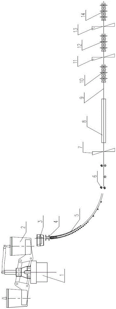
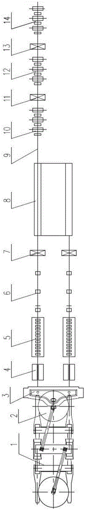
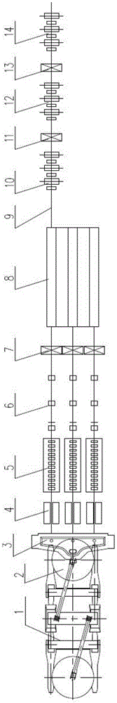
[0026] As shown in the figure, the wire and bar continuous casting and rolling production line in the present invention includes a continuous casting machine, a parallel flow device 8 and a rolling mill unit. The continuous casting machine is mainly composed of a rotary table 1, a ladle 2, a middle Package 3, crystallizer 4, secondary cooling section 5, tension leveler 6, cutting machine 7 and transport roller table 9, the rolling unit is mainly composed of rough rolling mill 10, middle rolling mill 12 and The finishing mill 14 is composed of 1# flying shear 11 between the rough rolling mill 10 and the middle rolling mill 12, 2# flying shear 13 between the middle rolling mill 12 and the finishing mill 14, and the parallel flow device 8 is arranged on the cutting machine 7 and rough rolling mill 10 between.

[0027] Specifically, the contin...


PUM


Abstract

The invention discloses a continuous casting and rolling production line of wire rods and a production method of the production line. The continuous casting and rolling production line of the wire rods comprises a continuous casting machine, a parallel-flow device and a rolling mill unit. The method comprises the steps that a square casting blank or a circular casting blank is produced by means of the continuous casting machine firstly, the produced square casting blank or circular blank is cut through a cutting machine, parallel flowing is conducted through the parallel-flow device, the parallel flowed square casting blank bodies or circular casting blank bodies are conveyed to an inlet of the rolling mill unit through a conveyor roller way finally, and the rods are prepared by rolling through a rough mill, an intermediate mill and a finishing mill in sequence. According to the continuous casting and rolling production line of the wire rods and the production method of the production line, seamless connection of the continuous casting machine and rolling mills is achieved, the casting blank can be directly hot-delivered into the rolling mill unit to be rolled into the rods, secondary heating through a heating furnace is not needed, and the continuous casting and rolling production line of the wire rods and the production method of the production line have the advantages of being high in pouring speed, small in casting machine flow number, compact in production rhythm, high in efficiency, less in energy consumption and low in construction investment and operation maintenance cost.

Description

technical field [0001] The invention belongs to the field of iron and steel metallurgy, and in particular relates to a continuous casting and rolling production line for wire and rod and a production method thereof. Background technique [0002] Wire rod is one of the most widely used steel products in engineering construction. The conventional production method is to use a multi-strand continuous casting machine to produce billets or round billets. After cutting the billets, they are sent to the heating furnace through hot delivery rollers. , the heating furnace heats the slab and sends it to the rolling mill for rolling. The specific process flow is as follows: Ladle → Tundish → Crystallizer → Secondary cooling section → Straightening machine → Cutting machine → Conveyor roller table → Steel transfer machine → Steel separating machine → Hot delivery roller table → Heating furnace bench → Heating furnace → rolling mill. Among them, the multi-strand slabs need to be transf...

Claims


Application Information

Patent Timeline
Patent Type & Authority Applications(China)
IPC IPC(8): B21B1/46
CPCB21B1/466
Inventor 王勇彭晓华刘志鹏李图学陈将孔意文韩志伟雷松陈南菲
Owner CISDI ENG CO LTD
Why Eureka
Try Eureka