

Ultrasonic coaxial auxiliary laser welding method for plate heat exchanger
A plate heat exchanger and laser-assisted technology, which is applied in the field of material processing, can solve the problems of reducing the utilization rate of ultrasonic vibration, cumbersome design and operation of side shafts, and the reduction of ultrasonic vibration effect, so as to avoid weld porosity defects, enhance joint strength and Corrosion resistance, the effect of improving the performance of welded joints
- Summary
- Abstract
- Description
- Claims
- Application Information
AI Technical Summary
Problems solved by technology
Method used
Image

Examples
Embodiment 1
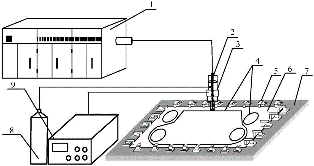
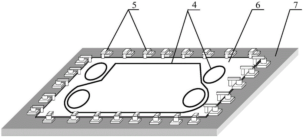
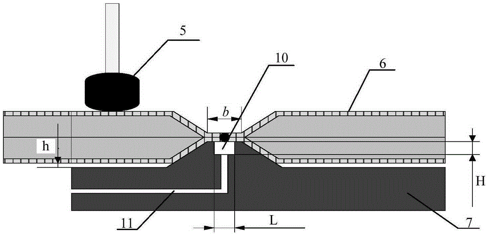
[0041] Such as figure 2 , 3 The schematic diagram of the laser welding auxiliary process equipment is shown. The design of the laser welding auxiliary process equipment is as follows: Since the welded part of the plate has a groove-like structure with a concave up and a convex down, in order to facilitate the clamping and positioning of the plate, strengthen the support at the weld bead, and improve the upper and lower The contact conditions of the plates at the weld bead facilitate the implementation of gas protection on the back of the weld. On the bottom plate of the welding workbench 7, a hole with a height 0.1 mm larger than the welding groove depth of the heat exchanger plate 6 is processed. Boss, and in the center of the boss, mill out a welding reserved groove 10 with a width not less than 3mm, at least 2mm smaller than the bottom of the welding groove, and a groove depth not exceeding 3mm; at the same time, welding protection is provided every 200-300mm The gas chan...
Embodiment 2
[0052] Such as figure 2 , 3 The schematic diagram of the laser welding auxiliary process equipment is shown. The design of the laser welding auxiliary process equipment is as follows: Since the welded part of the plate has a groove-like structure with a concave up and a convex down, in order to facilitate the clamping and positioning of the plate, strengthen the support at the weld bead, and improve the upper and lower The contact conditions of the plates at the weld bead facilitate the implementation of gas protection on the back of the weld. On the bottom plate of the welding workbench 7, a hole with a height 0.1 mm larger than the welding groove depth of the heat exchanger plate 6 is processed. Boss, and in the center of the boss, mill out a welding reserved groove 10 with a width not less than 3mm, at least 2mm smaller than the bottom of the welding groove, and a groove depth not exceeding 3mm; at the same time, welding protection is provided every 200-300mm The gas chan...
PUM
 Abstract
Description
Claims
Application Information