A manufacturing method of a marine low-speed diesel engine frame

A manufacturing method, diesel engine technology, applied in the direction of manufacturing tools, welding equipment, metal processing equipment, etc., can solve the problems of lack of welding strategy, cumbersome operation, and complicated welding process, so as to reduce the amount of later grinding and process time, facilitate transportation and Effects of hoisting, lowering callouts and deployment

Active Publication Date: 2017-12-26
CETC NINGBO MARINE ELECTRONICS RES INST
View PDF7 Cites 0 Cited by
  • Summary
  • Abstract
  • Description
  • Claims
  • Application Information

AI Technical Summary

Problems solved by technology

The document with the patent number ZL02145176.1 discloses a welding method for the frame of a low-speed diesel engine, mainly through a series of positioning holes, positioning iron pipes, and complicated devices such as straps and tire frames to complete the overall welding of the frame , but this method is cumbersome to operate and the consistency of the manufactured rack is poor
The document with the patent number ZL201010530701.8 discloses an automatic welding system for the frame frame of a marine diesel engine. The automatic welding method using real-time tracking welding replaces the traditional manual semi-automatic welding mode. This method realizes automation in the welding mode improvement, but lack of a certain welding strategy, low production efficiency and product interchangeability
[0003] The current known technology has the following defects: (1) the welding process is complicated, the efficiency is not high, the consistency between the same batch of racks is not good, and it is not suitable for mass production
(2) There is no structural modularization between the main modules of the rack, lack of interchangeability and versatility, local defects are likely to cause overall scrapping, and the manufacturing cost is high

Method used


Image

  • A manufacturing method of a marine low-speed diesel engine frame
  • A manufacturing method of a marine low-speed diesel engine frame
  • A manufacturing method of a marine low-speed diesel engine frame

Examples


Embodiment Construction

[0038] The present invention will be further explained below in conjunction with the accompanying drawings and specific embodiments.

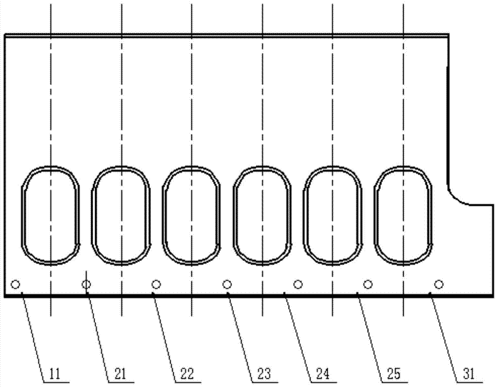
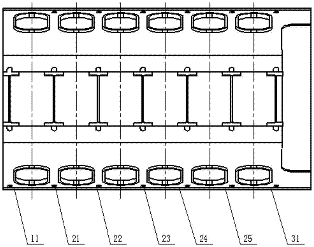
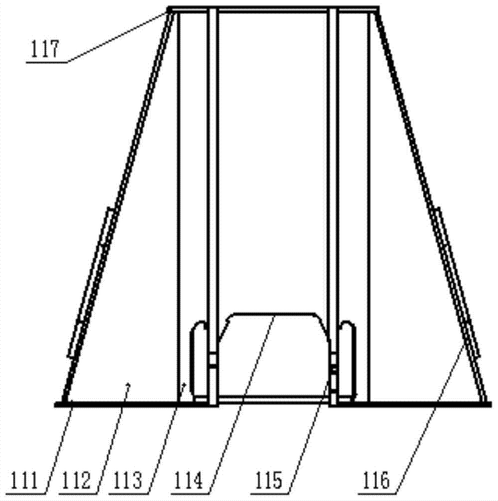
[0039] Such as Figure 1-4 Shown, the present invention mainly comprises the following steps:

[0040] The first step: if figure 1 , figure 2 and Figure 4The frame of a certain type of marine diesel engine shown can be divided into sections according to its structure: the first frame module 11; the middle frame A21, the middle frame B22, the middle frame C23, the frame middle D24 and the frame rack middle section E25; and rack tail section module 31. Wherein, the rack middle section module comprises five parts of rack middle section A21, rack middle section B22, rack middle section C23, rack middle section D24 and rack middle section E25, and because the rack middle section A21, rack middle section B22, and rack middle section C23 The five parts, the middle section of the rack D24 and the middle section of the rack E25 have exactly the s...


PUM


Abstract

The invention discloses a manufacturing method for a rack of a marine low-speed diesel engine. The manufacturing method comprises the following steps that firstly, the rack is divided into a rack head segment module, a rack middle segment module and a rack tail segment module, wherein the rack middle segment module comprises a plurality of rack middle segments which are the same in structure and size; secondly, according to the design size of the rack, all part plates of all the rack segments are cut for blanking, then grooves are processed and welded, and finally the plates are stored in a classified mode; thirdly, a CO2 welding method is adopted for welding the rack head segment module, the rack middle segment module and the rack tail segment module step by step respectively; fourthly, the rack head segment module, the rack middle segment module and the rack tail segment module are jointed and folded; and fifthly, annealing treatment is finally conducted on connection weld joints to reduce residual stress produced by welding of connection areas, and after overall heat treatment on the rack is completed, aging treatment and flaw detection are conducted to make the rack reach all design standards. The manufacturing method has the advantages of being high in production efficiency and good in interchangeability and universality.

Description

technical field [0001] The invention belongs to the technical field of diesel engines, and in particular relates to a manufacturing method for modular welding and integral splicing of a frame of a large marine low-speed diesel engine. Background technique [0002] As an important part of the diesel engine, the frame plays an important role in supporting the cylinder block and forming the crankcase with the machine base. The performance of the frame directly affects the reliability of the diesel engine. The document with the patent number ZL02145176.1 discloses a welding method for the frame of a low-speed diesel engine, mainly through a series of positioning holes, positioning iron pipes, and complicated devices such as straps and tire frames to complete the overall welding of the frame , but this method is cumbersome to operate and the consistency of the manufactured rack is poor. The document with the patent number ZL201010530701.8 discloses an automatic welding system fo...

Claims


Application Information

Patent Timeline
Patent Type & Authority Patents(China)
IPC IPC(8): B23K31/02B23K31/12
CPCB23K31/02B23K31/125
Inventor 唐文献张建刘焱周伟忠苏世杰晏飞
Owner CETC NINGBO MARINE ELECTRONICS RES INST
Why Eureka
Try Eureka