A 3d printing device
A 3D printing and printing head technology, applied in the field of 3D printing, can solve the problems of "support" limited carrying capacity, multi-material and printing time, product collapse, etc., to reduce the risk of collapse, improve printing efficiency, and eliminate delamination Effect
- Summary
- Abstract
- Description
- Claims
- Application Information
AI Technical Summary
Problems solved by technology
Method used
Image
Examples
Embodiment 1
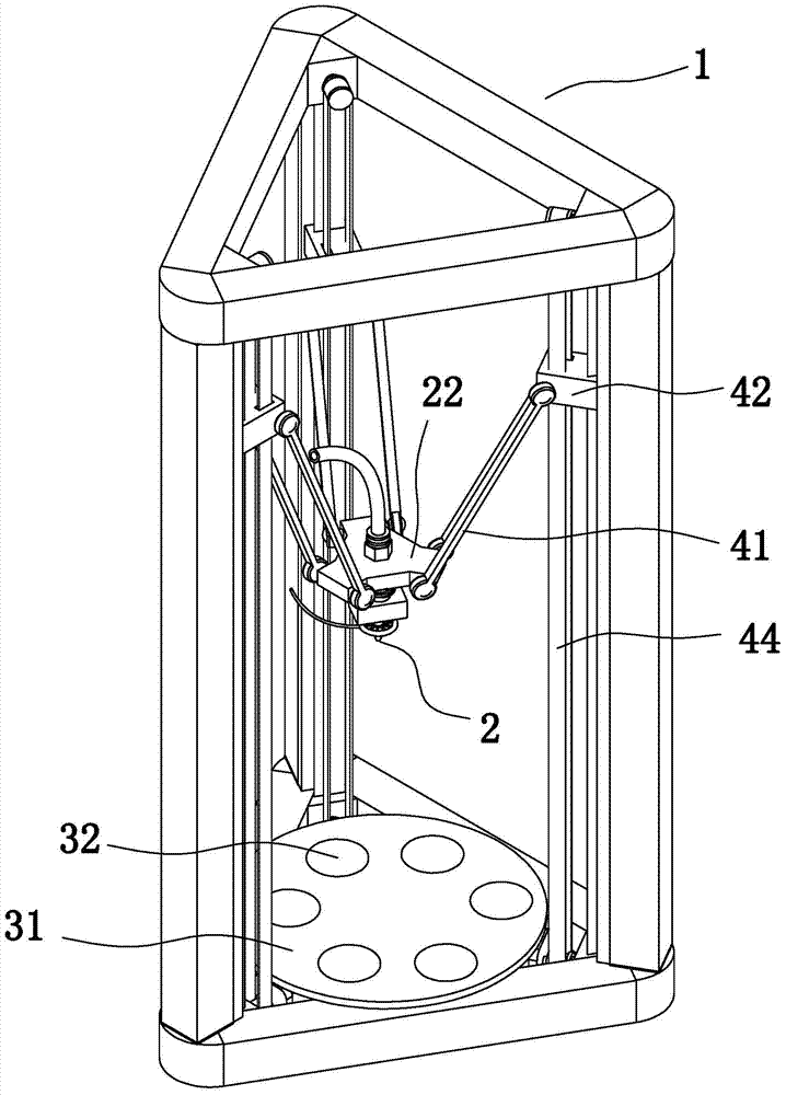
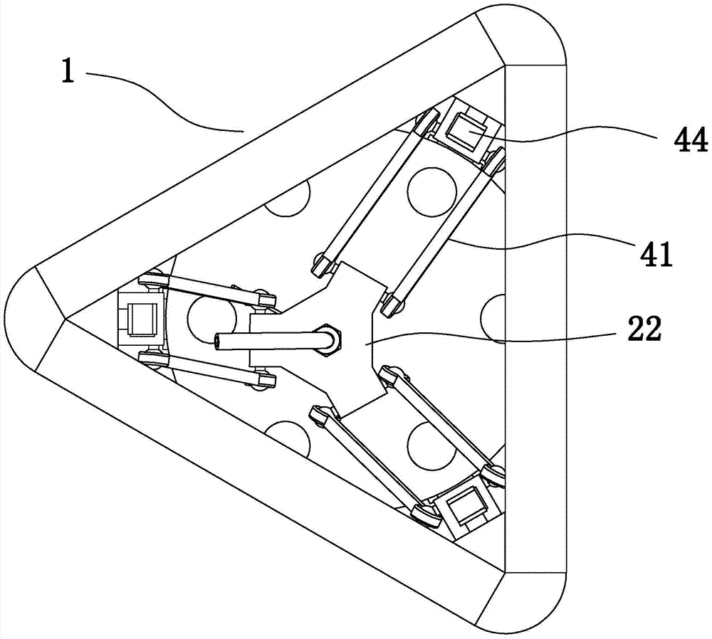
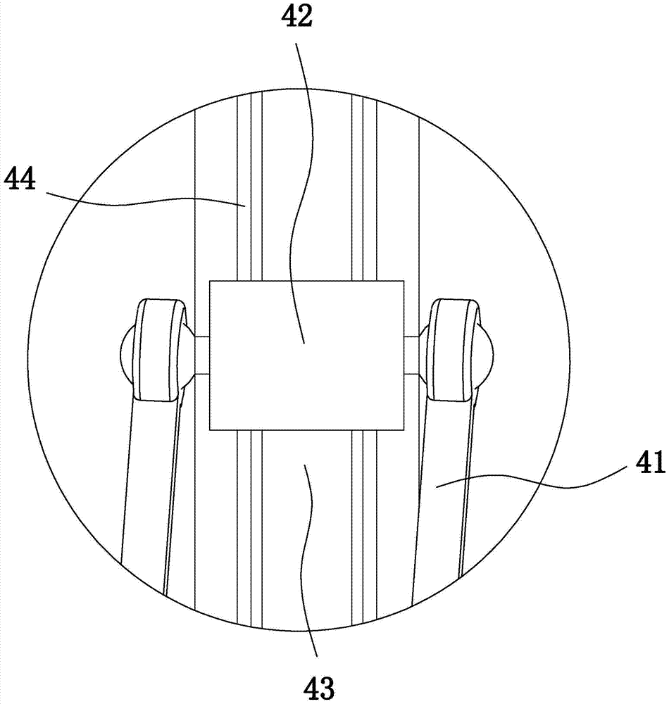
[0034] Embodiment 1: as Figure 1 to Figure 10 In the shown embodiment, a 3D printing device includes a main frame 1, a discharge printing head 2, a forming printing table 3, and also includes a printing head for driving the discharge printing head to move so as to change the position of the discharge printing head Displacement adjustment mechanism, the said discharge print head is provided with a print head feed end for inputting printing materials, said discharge print head is provided with a discharge channel 21 communicating with the print head feed end, said forming printing The stage includes a fixed platen 31 , at least one movable platen 32 that can move up and down, and a platen displacement adjustment mechanism corresponding to the movable platen and used to drive the movable platen to move up and down. The discharge printing head is used to output printing materials (such as molten plastic) to the forming printing table, and the printing head displacement adjustment...
Embodiment 2
[0040] Embodiment 2: In this implementation, the air cylinder / oil cylinder in Embodiment 1 is replaced by a servo air cylinder / servo oil cylinder. In addition, whether it is an air cylinder / oil cylinder or a servo cylinder / servo oil cylinder, as long as the height adjustment of the movable platen can be realized, any other commonly used adjustment mechanism, such as a screw mechanism, can also be used.
Embodiment 3
[0041] Embodiment 3: the basic structure and implementation mode of this embodiment are the same as embodiment 1, and its difference is:
[0042] like Figure 11 As shown in , the discharge channel is provided with a thermal insulation tube 23 coaxial with the discharge channel. The upper and lower ends of the thermal insulation tube are open. Thin material coloring channel 24 is formed between the wall and the channel wall of the discharge channel (that is, the inner wall of the discharge print head). The outlet of the coloring tube faces the outer wall of the heat-insulating tube, and a coloring check valve 521 is arranged at the outlet of the coloring tube. The passing direction of the coloring one-way valve is from the coloring pipe to the discharge channel, the highest point of the coloring port is lower than the highest point of the heat insulation cylinder, and the lowest point of the coloring port is higher than the lowest point of the heat insulation cylinder. The ve...
PUM
 Abstract
Description
Claims
Application Information
 - R&D
- Intellectual Property
- Life Sciences
- Materials
- Tech Scout
- Unparalleled Data Quality
- Higher Quality Content
- 60% Fewer Hallucinations
Browse by: Latest US Patents, China's latest patents, Technical Efficacy Thesaurus, Application Domain, Technology Topic, Popular Technical Reports.
© 2025 PatSnap. All rights reserved.Legal|Privacy policy|Modern Slavery Act Transparency Statement|Sitemap|About US| Contact US: help@patsnap.com


