Aerodynamic layout of aircraft with blended wing body

A technology of wing-body fusion and aerodynamic layout, which is applied in the field of aircraft, can solve the problems of increasing aircraft resistance, large thickness of the central fuselage, and affecting take-off and landing performance, so as to increase the maximum lift coefficient, increase the layout area, and improve take-off and landing performance. Effect

Inactive Publication Date: 2016-03-23
BEIJING AERONAUTIC SCI & TECH RES INST OF COMAC +1
View PDF5 Cites 3 Cited by
  • Summary
  • Abstract
  • Description
  • Claims
  • Application Information

AI Technical Summary

Problems solved by technology

[0004] 1. The BWB layout does not have a slender fuselage with a conventional layout, and the horizontal tail cannot be arranged. The tail edge must be used for trimming, and the control surface is arranged on the trailing edge of the wing; since the control surface is arranged on the trailing edge of the wing, the area of ​​the lifting device is large. Smaller than the conventional layout, resulting in a decrease in the maximum lift coefficient and affecting take-off and landing performance;
[0005] 2. The tail arm

Method used


Image

  • Aerodynamic layout of aircraft with blended wing body
  • Aerodynamic layout of aircraft with blended wing body
  • Aerodynamic layout of aircraft with blended wing body

Examples


Embodiment 1

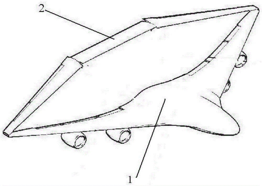
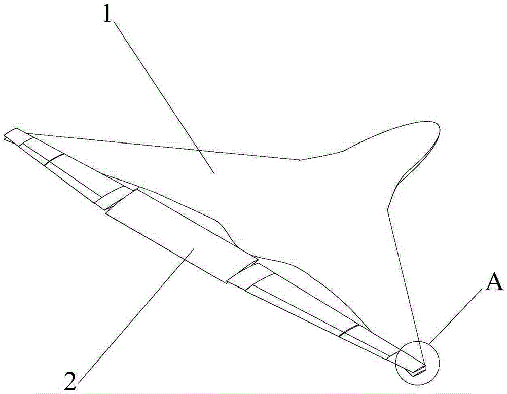
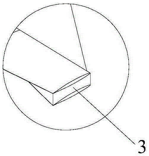
[0028] This embodiment provides an aerodynamic layout of a wing-body fusion aircraft, such as figure 1 Shown, it comprises wing-body fusion part, and the fuselage of wing-body fusion part fuses with wing and forms front wing 1, also comprises rear wing, and rear wing is flat tail 2, and the both sides of flat tail 2 and front machine The two sides of the wing 1 are respectively connected by connecting pieces 3 .

[0029] This embodiment is based on the aerodynamic layout of the wing-body fusion aircraft. The fuselage and the wings of the aircraft are integrated without obvious boundaries. Both the fuselage and the front wings can generate lift. Therefore, the original wing The fusion portion of the body is called the front wing. In this application, on the basis of wing-body fusion, adding a pair of flat tails as the rear wing can improve the lift of the wing-body fusion aircraft, and increase the layout area of ​​the lift-increasing device and the operating device, improve t...

Embodiment 2

[0035] This embodiment provides an aerodynamic layout of a wing-body fusion aircraft, the structure of which is basically the same as in Embodiment 1: comprising the wing-body fusion portion, the fuselage and the wing of the wing-body fusion portion merge to form the front wing, and also include The rear wing is a flat tail, and the two sides of the flat tail are respectively connected with the two sides of the front wing by connecting pieces.

[0036] The difference is that at least part of the flat tail is a full motion setup.

[0037] In the present embodiment, at least part of the flat tail is set with full motion, and the overall change of the flat tail can be made at a smaller angle in the cruising stage, so that the aircraft reaches a trim state, improves the rudder effect, and improves the longitudinal and directional maneuverability of the aircraft; the full-motion flat tail can also be It acts as a lift-increasing device to improve the take-off and landing performanc...

Embodiment 3

[0039] This embodiment provides an aerodynamic layout of a wing-body fusion aircraft, the structure of which is basically the same as in Embodiment 2: the wing-body fusion portion is included, the fuselage and the wing of the wing-body fusion portion are merged to form the front wing 1, and Including the rear wing, the rear wing is a horizontal tail 2, the two sides of the horizontal tail 2 are respectively connected with the two sides of the front wing 1 through the connecting piece 3, and at least part of the horizontal tail 2 is set for full motion.

[0040] Its difference: as Figure 4 As shown, it also includes at least two vertical tails 4, considering the simplicity and compactness of the aircraft structure, preferably, two vertical tails 4 are set, and the two ends of the two vertical tails 4 are connected to the rear end of the front wing 1 respectively. The horizontal tail 2 is connected, and the horizontal tail 2 placed between the two vertical tails 4 is a full-mot...


PUM


Abstract

The invention discloses an aerodynamic layout of an aircraft with a blended wing body and belongs to the technical field of aircrafts. The aerodynamic layout is designed for solving the problems that an existing aircraft with a blended wing body is insufficient in lift force and large in flight drag. The aerodynamic layout of the aircraft with the blended wing body involves the blended wing body and a rear wing; a fuselage and a wing of the blended wing body are blended to constitute a front wing; the rear wing is a horizontal tail, and the two sides of the horizontal tail are connected with the two sides of the front wing through connecting parts respectively. On the basis of wing and fuselage blending, the horizontal tail is added to serve as the rear wing so that the lift force of the aircraft with the blended wing body can be increased; in addition, the arrangement area of a high-lift device and the arrangement area of an operating device are increased so that the maximum lift coefficient can be increased and the take-off and landing performance of the aircraft can be improved.

Description

technical field [0001] The invention relates to the technical field of aircraft, in particular to an aerodynamic layout of a wing-body fusion aircraft. Background technique [0002] Economy is an important factor considered in the design of passenger aircraft. Aircraft designers pursue how to use less energy consumption to obtain greater lift resistance, longer range and more load on the basis of safety, comfort and environmental protection. passenger volume. The future large passenger aircraft puts forward higher requirements on the aerodynamic layout, and the conventional layout must increase the wing area and expand the loading space of the fuselage in order to increase the lift-to-drag ratio and increase the range. Aerodynamics bring many challenges, resulting in difficulties such as reduced weight efficiency and series development. Therefore, the innovation of aerodynamic layout plays a key role in improving the performance of large passenger aircraft. [0003] In rec...

Claims


Application Information

Patent Timeline
IPC IPC(8): B64C39/10B64C39/06
CPCB64C39/10B64C39/068
Inventor 夏明石伟峰张帅白璐
Owner BEIJING AERONAUTIC SCI & TECH RES INST OF COMAC
Why Eureka
Try Eureka