Method and device for water filling and pressure balance of extra-high-head gate

A high water head and gate technology, applied in water conservancy projects, hydropower, hydropower stations, etc., can solve the problems of inability to open the working valve, difficult handling, gate vibration, etc., to reduce the amount of dirt entering the water intake, which is conducive to safety. , the effect of reducing damage

Active Publication Date: 2016-03-23
CHINA POWER CONSRTUCTION GRP GUIYANG SURVEY & DESIGN INST CO LTD
View PDF6 Cites 11 Cited by
  • Summary
  • Abstract
  • Description
  • Claims
  • Application Information

AI Technical Summary

Problems solved by technology

For the water filling valve of the super-high water head accident gate, due to the large height of the gate (≥100m), there is a situation that the inlet of the water filling valve is stuck by dirt during the gate closing process, which will cause the water filling valve tube to be in a long-term leaking state. The state of water makes it very difficult to implement maintenance
In addition, setting the water filling valve on the top of the gate requires opening holes in the top main beam, which will weaken the cross section of the top main beam. When the water filling valve is in the open and over-current state during the gate closing process, it is easy to induce gate vibration and affect the safety of the gate structure.
Based on engineering safety considerations, there are also projects in China that use a bypass valve at the bottom of the dam body to fill the hydraulic pressure. However, due to the high operating water head and no pressure behind the valve, the working valve cannot be opened and fails. Later, water is taken from other places or the gate design is modified. Water filling valves and other means of filling water pressure are difficult to deal with and the effect is not good, so the existing technology is still not perfect

Method used


Image

  • Method and device for water filling and pressure balance of extra-high-head gate
  • Method and device for water filling and pressure balance of extra-high-head gate
  • Method and device for water filling and pressure balance of extra-high-head gate

Examples


Embodiment

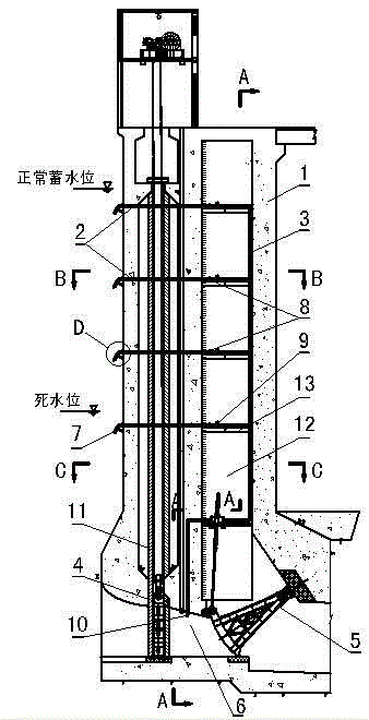
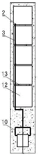
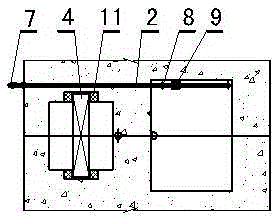
[0032] The method in this example is as Figure 1-5 As shown, during specific implementation, four layers of bypass pipelines 2 are arranged from top to bottom in the drainage structure 1 to converge to a main pipe 3 and then lead to the upper part of the drainage tunnel between the emergency gate 4 and the arc gate 5 On the side wall 6, and in the section from the entrance of each bypass pipeline 2 to the main pipe section along the water flow direction, set up the sewage and water intake device 7, the maintenance valve 8 and the working valve 9 in sequence. After the main pipe 3 leads to the upper part of the discharge tunnel chamber, it is divided into a Two branch pipes 10 of line symmetry. The topmost bypass pipeline is lower than the normal water storage level and completely submerged in the normal water storage level elevation water, and the bottommost bypass pipeline is lower than the dead water level and completely submerged in the dead water level elevation water. ...


PUM


Abstract

The invention discloses a method and a device for water filling and pressure balance of an extra-high-head gate. According to the method and the device, a group of uniformly distributed bypass pipelines is vertically arranged at an outlet structure according to an amplitude between a normal storage water level and a dead water level; a working valve is arranged on each bypass pipeline; outlets of all the working valves are converged to a main pipe, and water is introduced to a discharge tunnel between an emergency gate and a radial gate through the main pipe; when the emergency gate needs to be opened, the working valve in the closest position of a lower portion of the emergency gate is opened according to a reservoir water level elevation, and then water filling and pressure balance of the gate can be realized; no water filling valve needs to be arranged at the top of the gate, and therefore, a section of a top main beam can be kept complete; moreover, the gate is good in structural integrity and conductive to the safety of the gate structure. The method and the device for water filling and pressure balance of the extra-high-head gate are convenient to operate, and capable of reducing contaminations entering a water intake and ensuring normal water intaking of a reservoir area between the normal storage water level and the dead water level. Furthermore, no water filling valve needs to be arranged at the top of the gate, so that the completeness and integrity of the gate structure can be ensured to be conductive to the safety of the gate structure and the discharge tunnel.

Description

technical field [0001] The invention relates to a method and a device for filling hydraulic pressure of an ultra-high water head gate, belonging to the technical field of gates of water conservancy and hydropower projects. Background technique [0002] In water conservancy and hydropower projects, for the super-high water head drainage channels with low positions such as flood discharge tunnels, vent holes and vent bottom holes, plane emergency gates are generally set at the entrance, and arc-shaped working gates are set at the exit. When the operation of the shaped working gate fails or the discharge channel needs to be overhauled, it will be closed, and it will be opened after the accident is dealt with or overhauled. Because the operating conditions of the accident gate are: dynamic closing and static opening, a water filling valve is generally installed on the top of the plane emergency gate for filling hydraulic pressure. For the water filling valve of the super-high w...

Claims


Application Information

Patent Timeline
Patent Type & Authority Applications(China)
IPC IPC(8): E02B9/06
CPCE02B9/06Y02E10/20
Inventor 王兴恩
Owner CHINA POWER CONSRTUCTION GRP GUIYANG SURVEY & DESIGN INST CO LTD
Why Eureka
Try Eureka