A small segmental approach filling mining method for vertical middle and deep hole falling

A technology of approach filling and mining method, which is applied in ground mining, underground mining, special mining, etc. It can solve the problems of large empty side of the mine, high mining cost, and hanging upside down on dangerous rocks, so as to achieve a high degree of safety in the operating environment, The effect of reducing the amount of accurate engineering and leveling and smooth support

Active Publication Date: 2018-03-02
南京银茂铅锌矿业有限公司
View PDF6 Cites 0 Cited by
  • Summary
  • Abstract
  • Description
  • Claims
  • Application Information

AI Technical Summary

Problems solved by technology

The upward approach filling mining method has a small exposed area of ​​the stope roof, but it requires a large amount of mining engineering, many filling retaining walls are erected, the mining operation efficiency is low, and filling and roof connection is difficult, so it is difficult to use in some mines. This method is suitable for The mining cost of ore bodies with higher value and richer grades is relatively high for general non-ferrous metal mines, which is not conducive to cost control
Although the segmented filling mining method also avoids the way that rock drilling and blasting operators work in an environment with a large exposed area of ​​the roof, it adopts fan-shaped blast holes, and the upper and lower segmented rock drilling roadways

Method used


Image

  • A small segmental approach filling mining method for vertical middle and deep hole falling
  • A small segmental approach filling mining method for vertical middle and deep hole falling
  • A small segmental approach filling mining method for vertical middle and deep hole falling

Examples


Embodiment Construction

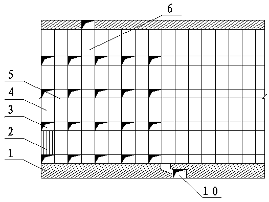
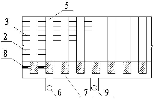
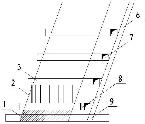
[0031] The construction scheme of the arrangement method for the vertical medium-deep hole small-section approach proposed by the present invention is as follows:

[0032] (1) Stope cutting:

[0033] Both the segmental connecting roadway and the rock drilling approach are located above the bottom pillar of the stope, and the segmental connecting roadway is 5 to 8 meters away from the chassis ore-rock boundary. Slide the mine shaft and the return air filling shaft that runs through the upper middle section of the transport level roadway, and then dig a segmented rock drilling roadway with a relatively large width and height from the vertical ore body of the segmental contact roadway to the upper wall every 3 to 5 meters, and the segmented rock drilling roadway During excavation, smooth blasting should be used for the surrounding holes, and the unstable area in the roof of the upper rock drilling roadway needs to be supported by anchor nets.

[0034] (2) Rock drilling and blast...


PUM


Abstract

The invention discloses a mining method employing sublevel filling during medium-depth holes blasting in stoping accesses. Top-bottom sectionalized drilling drifts in the same stoping access are aligned; vertical medium-depth holes are drilled in the top sectionalized drilling drift during stoping; millisecond blasting is adopted so as to reduce the explosive consumption for one time; periphery holes of the top sectionalized drilling drift and vertical side holes of two sides of the stoping access are subjected to smooth blasting; a local unstable area of a support plate is supported in time, so that the access top plate and the two sides of a mined-out area after blasting are flat and smooth; the phenomenon that large blocks overhang and protruding of the side walls is avoided; meanwhile, small sections and arched support plates are adopted, and broken ores left in the field balance the deformation of the two sides of the mined-out area, so that the ground pressure of the mined-out area is managed in a reasonable and economical way. The powerful safety guarantee is provided for carry-scrapers when the carry-scrapers enter the mined-out area and carry the ores. According to the mining method, the layout is simple and feasible, the operation efficiency is high, and the ratio of drifting meters over mining tonnages and the stoping cost are low. The mining method is easy to popularize in small and medium-sized non-ferrous metal mines.

Description

technical field [0001] The invention relates to the underground mining technology of metal mines, especially the approach-type filling mining method. Background technique [0002] Avoiding rock drilling and blasting operators working for a long time in a space with a large exposed area of ​​the roof is the most effective method to prevent roof fall accidents in stopes and ensure safe production in mining. The upward approach filling mining method has a small exposed area of ​​the stope roof, but it requires a large amount of mining engineering, many filling retaining walls are erected, the mining operation efficiency is low, and filling and roof connection is difficult, so it is difficult to use in some mines. This method is suitable for The mining cost of ore bodies with higher value and richer grades is relatively high for general non-ferrous metal mines, which is not conducive to cost control. Although the segmented filling mining method also avoids the way that rock dri...

Claims


Application Information

Patent Timeline
IPC IPC(8): E21C41/22
CPCE21C41/22
Inventor 焦鹏曹维勤张文如刘乾勇朱高杰
Owner 南京银茂铅锌矿业有限公司
Why Eureka
Try Eureka