
Template supporting device for concrete supporting construction of shaft and lane engineering

A kind of concrete and engineering technology, which is applied in shaft equipment, shaft lining, earthwork drilling and mining, etc. It can solve the problems of traffic, inconvenient construction, labor-intensive production and installation, and low construction efficiency, so as to improve labor productivity, stabilize and firm the structure, and save energy. wood effect

Active Publication Date: 2016-03-23
MAGANG (GROUP) HOLDING CO LTD
View PDF4 Cites 4 Cited by
  • Summary
  • Abstract
  • Description
  • Claims
  • Application Information

AI Technical Summary

Problems solved by technology

The disadvantage is that the roadway is blocked, and it takes a long time. All the supports need to be removed after the concrete is solidified, and then the next step of excavation or support process is entered. The construction efficiency is low, and the traffic and construction are inconvenient; the horizontal support, vertical support, keel and formwork are multi-purpose Wood production, production and installation are labor-intensive, time-consuming, wood consumption is high, and resources are seriously wasted

Method used


Image

  • Template supporting device for concrete supporting construction of shaft and lane engineering
  • Template supporting device for concrete supporting construction of shaft and lane engineering
  • Template supporting device for concrete supporting construction of shaft and lane engineering

Examples


Embodiment Construction

[0023] Below in conjunction with embodiment the present invention is described in further detail:

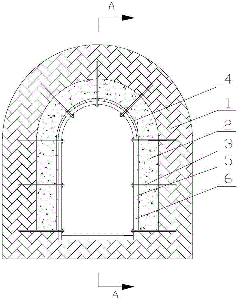
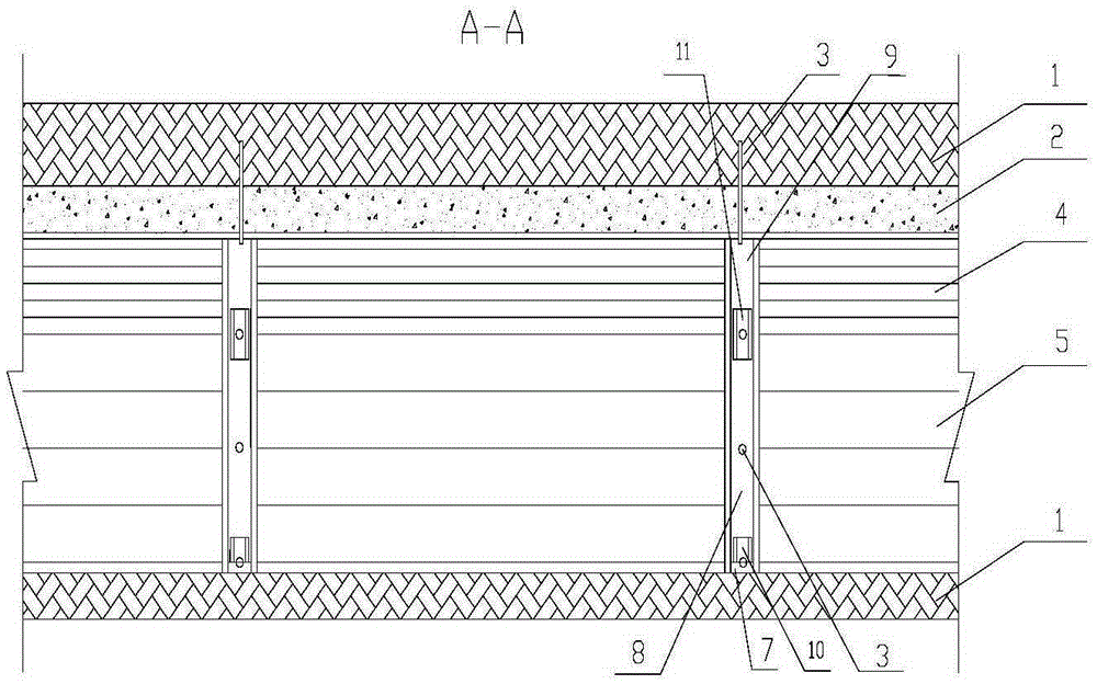
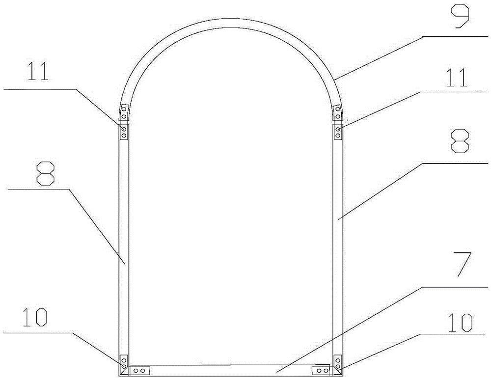
[0024] Depend on figure 1 , figure 2 , image 3 , Figure 4 , Figure 5 , Figure 6 It can be seen that the formwork device for the concrete support construction of the shaft engineering includes a wall formwork 5 and a vault formwork 4, and the formwork device is composed of a steel keel 6 and a fixed anchor rod 3; And the vault beam 9 is made of channel steel, and the cross brace, column and vault beam are connected by the wall bottom connector 10 and the wall top connector 11 to form a high-strength airtight steel keel; the fixed anchor rod is composed of a rod body 12, a cover plate 15 and nut 16; the steel keel is positioned on the rod body 12 by the cover plate and the nut, and the rod body is firmly fixed in the surrounding rock 1 by the anchoring agent 14 through the drill hole 13; Installed at intervals of 1500mm; the wall formwork and vault formwork are installe...


PUM


Abstract

The invention discloses a template supporting device for concrete supporting construction of shaft and lane engineering and relates to a template supporting device for cast-in-place concrete of shaft and lane engineering. The template supporting device comprises wall templates and a vault template and is characterized in that the template supporting device comprises steel joists and fixing anchor rods, wherein each steel joint comprises a cross arm, stand columns and a vault beam; each fixing anchor rod comprises a rod body, a cover plate and a nut; the steel joints are mounted at intervals in the length direction of the poured concrete roadway, and the rod bodies penetrate through the steel joists and are fixed in surrounding rock; the wall templates and the vault template are laid on two steel joists, concrete is poured between the surrounding rock and the templates, and the wall templates and the vault template are laid sequentially with increasing of height of the poured concrete; the steel joists are dismounted after concrete setting, the concrete surface is covered with the cover plate, and composite supporting is formed. The template supporting device has the advantages that the template supporting device is novel in concept, stable and firm in structure, simple to manufacture, convenient to mount and capable of being repeatedly used and wood materials are saved; the roadway is unimpeded, the construction is convenient, and the production efficiency is improved; the strength of the steel joists is high and integrally connected with the surrounding rock to form a stereoscopic structure, and the strength of the supporting device is greatly improved.

Description

technical field [0001] The invention belongs to the technical field of concrete support, and in particular relates to cast-in-place concrete and reinforced concrete support formwork devices for shaft engineering. Background technique [0002] Cast-in-place concrete and cast-in-place reinforced concrete support is an important structural form in the permanent support of shaft engineering. It is often used in horse head gates, substation chambers, water pump room chambers, and crushing chambers that require higher support levels. The engineering support of wells and roadways with relatively high crushing degree of surrounding rocks. In the traditional cast-in-place concrete support, it is necessary to erect multiple horizontal supports and vertical supports in the roadway to fix the formwork keel, install wall formwork and vault formwork on the keel, and pour concrete. The disadvantage is that the roadway is blocked and takes a long time. It is necessary to wait until the con...

Claims


Application Information

Patent Timeline
Patent Type & Authority Applications(China)
IPC IPC(8): E21D11/10
CPCE21D11/102E21D11/107
Inventor 董亚宁
Owner MAGANG (GROUP) HOLDING CO LTD
Learn More