Intelligent cooling system based on split cooling and reverse cooling for engine, and control method

A cooling system and engine technology, applied in the direction of engine cooling, coolant flow control, cooling device control device, etc., can solve the problem that the cooling intensity of the cylinder head and cylinder liner cannot be independently adjusted, and the cooling intensity of the cylinder head and cylinder liner is unfavorable , cylinder liner overcooling and other problems, to reduce overcooling phenomenon, improve fuel economy and improve cooling intensity

Active Publication Date: 2016-03-23
ZHEJIANG UNIV
View PDF5 Cites 20 Cited by
  • Summary
  • Abstract
  • Description
  • Claims
  • Application Information

AI Technical Summary

Problems solved by technology

[0003] In the traditional cooling system, an integrated water jacket is adopted for the cooling of the cylinder head and the cylinder liner. The heat load is higher than that of the cylinder liner. This cooling method cannot independently adjust the cooling intensity of the cylinder head and cylinder liner, so it will cause insufficient cooling of the cylinder head or excessive cooling of the cylinder liner.
At the same time, the coolant first cools the cylinder liner and then cools the cylinder head, which will inevitably cause the temperature of the cylinder head water jacket coolant to be higher than that of the cylinder liner water jacket coolant, which is not conducive to the reasonable control of the cooling intensity of the cylinder head and cylinder liner.

Method used


Image

  • Intelligent cooling system based on split cooling and reverse cooling for engine, and control method
  • Intelligent cooling system based on split cooling and reverse cooling for engine, and control method
  • Intelligent cooling system based on split cooling and reverse cooling for engine, and control method

Examples


Embodiment Construction

[0026] The present invention will be described in further detail below in conjunction with the accompanying drawings, but not as a limitation of the present invention.

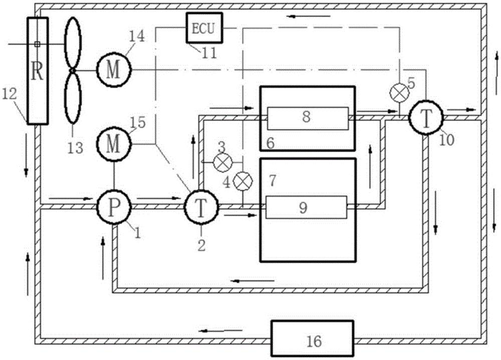
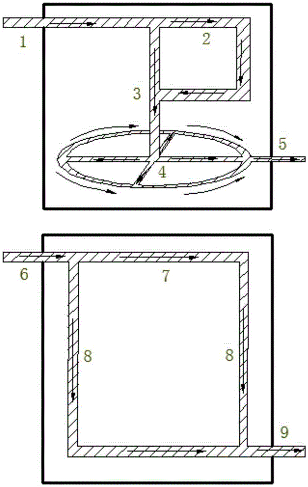
[0027] This cooling system model mainly includes the internal cooling water jacket (cylinder head, body cooling water jacket), external cooling system accessories (electrically controlled water pump, electronically controlled fan, electronically controlled thermostat, expansion tank) and electronic control part (ECU ,Temperature Sensor)

[0028] Such as figure 1 As shown, an engine intelligent cooling system based on engine split cooling and reverse cooling includes an electronically controlled water pump, a first electronically controlled thermostat, a second electronically controlled thermostat, an electronically controlled fan, an expansion tank, a cylinder head water cover, body water jacket, first temperature sensor, second temperature sensor, third temperature sensor, first motor, second motor and elect...


PUM


Abstract

The invention discloses an intelligent cooling system based on split cooling and reverse cooling for an engine, and a control method. The cooling system comprises a cylinder cover water jacket, a body water jacket, an electronically-controlled water pump, electronic thermostats, an electronically-controlled fan, a heat dissipater, an expansion water tank, temperature sensors, motors and an electronic control unit. During a working process of the system, the electronically-controlled water pump pumps a cooling liquid in the engine, the first electronic thermostat controls the cooling liquid to enter the cylinder cover water jacket and the body water jacket according to cooling liquid temperature signals of a cylinder cover and a body respectively, flow from top down, and flow out after the cooling the cylinder cover and the body; and the second electronic thermostat distributes the flow rate of the cooling liquid entering large circulation and small circulation according to a cooling liquid temperature of a main tube, and the cooling liquid is circulated and then pumped in the engine to cool. The cooling system disclosed by the invention is capable of accurately distributing the flow rate of the cooling liquid in the cylinder body and the body of the engine, reducing the phenomenon of non-uniform cooling, and shortening the warm-up time of the engine; and the heat states of heated components are optimized through the reverse cooling.

Description

technical field [0001] The invention relates to an engine intelligent cooling system and a control method, in particular to an engine intelligent cooling system combined with cylinder head body split cooling technology and reverse cooling technology Background technique [0002] As the power density of diesel engines and the explosion pressure in the cylinder continue to increase, the thermal load of heated parts including cylinder heads and cylinder liners continues to increase, and the number of thermal failure cases is gradually increasing. At the same time, the direction of energy saving and emission reduction of diesel engines is The general trend. Therefore, the continuous development of diesel engines puts forward stricter requirements on its reliability, fuel economy and emission performance. Therefore, the cooling system should provide sufficient cooling strength for the high heat load area to ensure its thermal reliability, and at the same time reduce the heat load...

Claims


Application Information

Patent Timeline
Patent Type & Authority Applications(China)
IPC IPC(8): F01P3/02F01P7/16F01P7/04
CPCF01P3/02F01P7/048F01P7/164F01P7/165F01P7/167F01P2003/027F01P2025/50F01P2037/02
Inventor 俞小莉陈晓强黄瑞刘震涛黄钰期孙正奕冬陆永升
Owner ZHEJIANG UNIV
Why Eureka
Try Eureka