Fuel-supply system

A technology of fuel supply device and fuel pressure, which is applied in the direction of liquid fuel feeder, fuel injection control, charging system, etc. It can solve the problems of large fuel pump ejection capacity, large power consumption, overpressure, etc., and achieve reduction Effects of overpressure, reduction of power consumption, and prevention of overpressure

Active Publication Date: 2016-03-23
AISAN IND CO LTD
View PDF8 Cites 2 Cited by
  • Summary
  • Abstract
  • Description
  • Claims
  • Application Information

AI Technical Summary

Problems solved by technology

However, when the duty cycle of the electric motor is set to the maximum value, the discharge capacity of the fuel pump is maximum, so if Figure 11 As shown in the center of the , the following problems occur: an overpressure of the fuel pressure occurs, or an increase in power consumption occurs

Method used


Image

  • Fuel-supply system
  • Fuel-supply system
  • Fuel-supply system

Examples


Embodiment approach 1

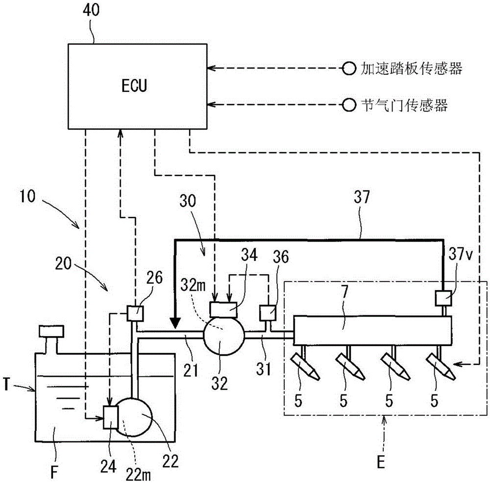
[0031] Below, based on Figure 1 to Figure 4 The fuel supply device 10 according to Embodiment 1 of the present invention will be described. The fuel supply device 10 of the present embodiment is a device for supplying the fuel F stored in the fuel tank T of the automobile to the engine E. As shown in FIG.

[0032]

[0033] Such as figure 1 As shown, the fuel supply device 10 according to the present embodiment includes a low-pressure fuel pump unit 20 and a high-pressure fuel pump unit 30 connected in series. The low-pressure fuel pump unit 20 and the high-pressure fuel pump unit 30 are configured to be able to control fuel pressure (hereinafter referred to as fuel pressure) based on a signal received from an engine control unit ECU (hereinafter referred to as ECU 40 ). Here, electric power is supplied from the battery to the low-pressure fuel pump unit 20 , the high-pressure fuel pump unit 30 , and the ECU 40 by turning on an ignition switch (not shown) of the vehicle. ...

Embodiment approach 2

[0045] Below, based on Figure 5 to Figure 10 A fuel supply device according to Embodiment 2 of the present invention will be described. The fuel supply device according to the present embodiment is an improvement of the fuel pressure control (fuel pressure control during time T0 to T1 ) using the provisional target fuel pressure value Ps in the fuel supply device 10 according to the first embodiment. As a result, the basic structure of the fuel supply device is the same as that of the fuel supply device 10 according to the first embodiment.

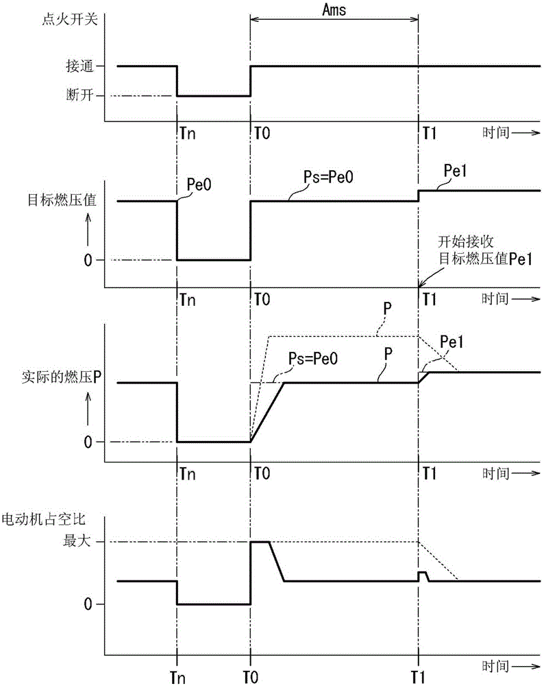
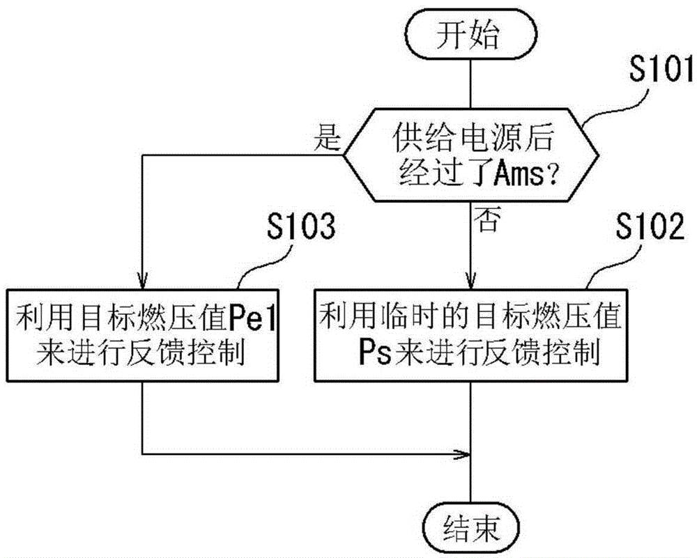
[0046] Such as Figure 5 As shown, in the fuel supply device (low pressure control unit 24 ) according to the present embodiment, when the ignition switch is turned on (time T0 ), the temporary target fuel pressure value Ps is set similarly to the case of the first embodiment. Moreover, the microcomputer of the low-voltage control unit 24 executes Figure 6 The process shown in the flowchart. For example, if Figure 5 As shown, at t...


PUM


Abstract

The invention provides a fuel-supply system. The invention aims to realize a fact that a pressure control part can properly control a fuel pressure before reception of a target fuel pressure from a control device. The fuel-supply system is provided with the components of a fuel pump which is driven through a motor and pressurizes the fuel in a fuel tank for conveying the pressurized fuel to an engine; a pressure control part which performs feedback control on voltage which is applied by the motor so that the fuel pressure approaches a target fuel pressure; the control device which transmits the target fuel pressure to the pressure control part; and a power supply device which supplies electric power to the motor, the pressure control part and the control device. After the switch of the power supply device is switched on (at a time point T0) and before the target fuel pressure (Pel) is received by the pressure control part from the control device (at a time point T1), the pressure control part utilizes a temporary target fuel pressure (Ps) for performing feedback control on the fuel pressure (P).

Description

technical field [0001] The present invention relates to a fuel supply device which feedback-controls the voltage applied to a motor of a fuel pump so that an actual fuel pressure approaches a target fuel pressure value. Background technique [0002] Patent Document 1 describes a related conventional fuel supply device. This fuel supply device is a device for pressurizing and feeding fuel in a fuel tank of an automobile to an engine. The fuel supply device includes a fuel pump driven by an electric motor, and a pressure control unit that controls the pressure (fuel pressure) of fuel injected from the fuel pump. The pressure control unit feedback-controls the duty ratio of the electric motor of the fuel pump so that the actual fuel pressure approaches a target fuel pressure value (target fuel pressure value) received from an engine control unit (ECU). Here, the electric power is supplied from the battery to the ECU, the motor, and the pressure control unit by turning on the ...

Claims


Application Information

Patent Timeline
Patent Type & Authority Applications(China)
IPC IPC(8): F02D41/02F02M37/08
CPCF02M37/08F02D33/006F02D41/061F02D41/3082F02D41/3809F02D2200/0602F02D2250/31F02M2037/087
Inventor 田川直行秋田实
Owner AISAN IND CO LTD
Why Eureka
Try Eureka