Gas explosion impact force detecting device and method

A gas explosion and detection device technology, applied to measuring devices, material analysis through optical means, instruments, etc., can solve problems such as damage, difficult explosion impact, difficulty in meeting actual needs, etc., and achieve accurate control of outburst time and exit opening time Short, the effect of improving the level of protection technology and equipment

Inactive Publication Date: 2016-03-23
SHANDONG UNIV OF SCI & TECH
View PDF6 Cites 6 Cited by
  • Summary
  • Abstract
  • Description
  • Claims
  • Application Information

AI Technical Summary

Problems solved by technology

[0004] There are many coal mines in our country, and gas accidents occur frequently. To study the impact of the gas explosion, what kind of damage it can cause, what degree of damage, and whether the mine is strong enough, these require advanced test equipment for simulation and analysis. Most of the experimental devices are relatively primitive or relatively simple, and the basis for judging is whether the explosion-proof membrane has burst, how many layers have burst, and the state of the burst, etc. It is difficult to study the specific situation of the explosion impact based on this
Difficult to meet actual needs

Method used


Image

  • Gas explosion impact force detecting device and method

Examples


Embodiment 1

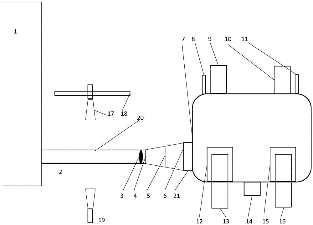
[0043] A gas explosion impulse detection device, characterized in that:

[0044] The detection device includes a buffer bin, a blast vent pipe, a pipeline, a blast bin, and a camera unit;

[0045] Among them, the volume of the buffer chamber is 30 times that of the blasting chamber, the material is made of steel, the interior is coated with flame-retardant materials, and the exterior is coated with anti-rust paint;

[0046] The explosion-venting pipe connects the pipeline and the blasting chamber, and the explosion-venting pipe is provided with a first explosion-venting membrane, a second explosion-venting membrane, The third explosion-venting membrane;

[0047] The pipeline is an explosion-proof material pipeline, and the explosion-proof material is transparent. A sliding vane chute and a sliding vane are arranged in the pipeline, and the sliding vanes are clamped in four sliding vane chutes arranged symmetrically on the inside parallel to the pipeline, and Under the shock ...

Embodiment 2

[0067] A gas explosion impulse detection device, characterized in that:

[0068] The detection device includes a buffer bin, a blast vent pipe, a pipeline, a blast bin, and a camera unit;

[0069] Among them, the volume of the buffer chamber is 20 times that of the blasting chamber, the material is made of stainless steel, the interior is coated with flame-retardant materials, and the exterior is coated with anti-rust paint;

[0070] The explosion-venting pipe connects the pipeline and the blasting chamber, and the explosion-venting pipe is provided with a first explosion-venting membrane, a second explosion-venting membrane, The third explosion-venting membrane;

[0071] The pipeline is an explosion-proof material pipeline, and the explosion-proof material is transparent. A sliding vane chute and a sliding vane are arranged in the pipeline, and the sliding vanes are clamped in four sliding vane chutes arranged symmetrically on the inside parallel to the pipeline, and Under ...


PUM


Abstract

The invention provides an experiment device capable of materializing and concreting impact force caused by explosions, and particularly provides a gas explosion impact force detecting device. According to the specific scheme, the device is characterized by comprising a buffer bin, a vent duct, a pipeline, an explosion bin and a camera part, the buffer bin is made of steel, the vent duct is connected with the pipeline and the explosion bin and provided with a vent film, the pipeline is an anti-explosion material pipeline and is transparent, the pipeline is internally provided with slip sheet chutes and slip sheets, the slip sheets are clamped in the chutes and can be pushed to slide, the explosion bin is the place where gas explosions are triggered, and the camera part comprises a movement camera, a movement camera bracket and a static camera. The invention further provides a gas explosion impact force detecting method using the gas explosion impact force detecting device.

Description

technical field [0001] The invention relates to the technical field of blasting test devices and methods, in particular to a specially designed gas explosion impulse detection device and detection method. Background technique [0002] Coal and gas outburst is one of the most serious disasters in coal mining in my country. The dynamic effect produced when the outburst occurs can destroy the production system, cause casualties, and easily cause major accidents such as coal dust and gas explosions. Therefore, in order to minimize the destructive effects of disasters, it is necessary to study the disaster-causing mechanism of coal and gas outbursts and explore effective disaster control methods and measures. [0003] Due to the complexity of coal and gas outburst and the limitations of research methods and means, there are few theoretical studies on the disaster-causing theory of coal and gas outburst at home and abroad. There are insurmountable difficulties in laboratory simu...

Claims


Application Information

Patent Timeline
Patent Type & Authority Applications(China)
IPC IPC(8): G01N21/84
CPCG01N21/84
Inventor 马鹤田和强李光蒋佳坤
Owner SHANDONG UNIV OF SCI & TECH
Why Eureka
Try Eureka