Integrated testing stand for linear motors

The technology of a comprehensive test bench and a linear motor, which is applied in the field of a linear motor comprehensive test bench, can solve the problems that the present invention is not the closest to the prior art, and achieve the effects of real-time monitoring of efficiency, synchronous adjustment, and simple operation

Inactive Publication Date: 2016-03-23
TONGJI UNIV
View PDF5 Cites 8 Cited by
  • Summary
  • Abstract
  • Description
  • Claims
  • Application Information

AI Technical Summary

Problems solved by technology

At present, there is no application case of this test bench, and the present invention is not the closest to the prior art

Method used


Image

  • Integrated testing stand for linear motors
  • Integrated testing stand for linear motors

Examples


Embodiment Construction

[0017] The present invention will be further described in detail below in conjunction with the accompanying drawings and specific embodiments.

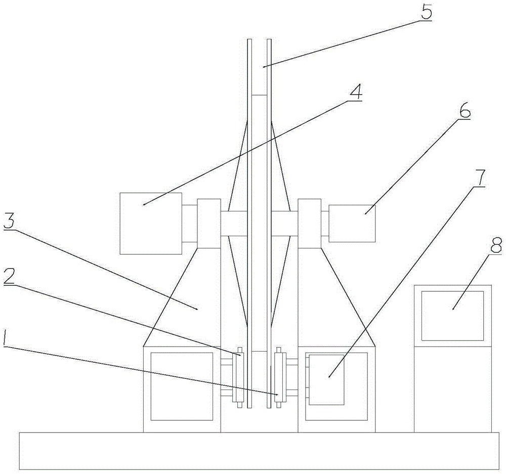
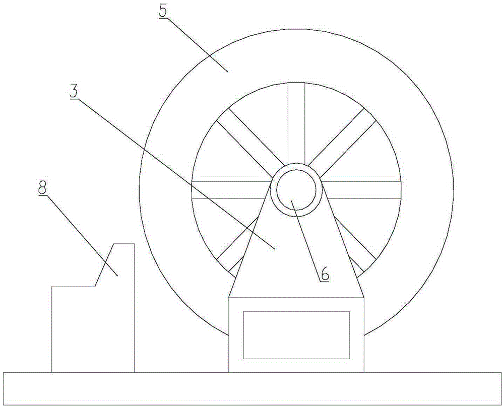
[0018] The linear motor comprehensive test bench of the present invention adopts the principle and method of a common asynchronous linear motor test with a short stator and a long rotor. The short stator with windings is fixed on the follower mechanism 7, and the long rotor adopts a steel and aluminum composite magnetic isolation structure. Inside the rotor is an induction plate, the diameter of the composite rotor is about 8 meters, and the test bench is large in size.

[0019] Such as figure 1 , figure 2 Shown:

[0020] Fix the linear motor, various sensors, and the rotor induction board through the mounting bracket. The air gap between the rotor induction plate and the stator is adjustable in the range of 6-15mm.

[0021] The follow-up mechanism 7 is installed on the lower part of the support base 3, and is a set of lateral sl...


PUM


Abstract

The invention relates to an integrated testing stand for linear motors. The testing stand is characterized by comprising two linear motors arranged symmetrically, a composite rotor placed between the two linear rotors, a pair of supporting seats and a pair of servo mechanisms, wherein the two linear motors include a right motor and a left rotor; the composite rotor is arranged in the vertical direction and mounted on the supporting seats via a pin of the rotor; the right rotor and the left rotor are arranged symmetrically by taking the composite rotor as the center; the two servo mechanisms are also arranged symmetrically by taking the composite rotor as the center, and move simultaneously in the opposite directions, and the servo mechanisms are fixed to the linear motors respectively, so that the normal force of the right motor and that of the left motor are offset; and each servo mechanism includes a transverse sliding control and locking device, is mounted in the lower portion of the corresponding supporting seat, and is used to implement transverse movement and positioning on the corresponding linear motor. The integrated testing stand can be used to test and research the traction force, the normal force, the braking force, the driving power, the motor gap and the like of the linear motors, and can serve as a tester for the traction linear motors of automobile.

Description

technical field [0001] The invention relates to a linear motor comprehensive test bench, which belongs to the technical field of rail transit linear motor testing. It is used for the test and test of the traction drive, braking system and suspension system of medium and low speed maglev vehicles, as well as the comprehensive test and test of rail transit linear motors. Background technique [0002] The traction drive, braking system and suspension system of medium and low-speed maglev vehicles are the prerequisites to ensure the safe operation of the train. In addition to the track accuracy and train load affecting the stable suspension of the train, the interaction force between the stator and rotor of the traction linear motor, that is, the motor method The vertical force is also a key factor affecting the stable suspension of the train. Eliminating the influence of the normal force of the motor, or reducing the influence of the normal force to a minimum, contributes to t...

Claims


Application Information

Patent Timeline
Patent Type & Authority Applications(China)
IPC IPC(8): G01R31/34
CPCG01R31/34
Inventor 杨新斌孙晨
Owner TONGJI UNIV
Why Eureka
Try Eureka