Radio frequency channel real-time calibration method and secondary radar

A technology of secondary radar and calibration method, applied in the field of electronics, which can solve the problems of adjusting the consistency of the amplitude and phase of the radio frequency channel

Inactive Publication Date: 2016-03-23
SICHUAN JIUZHOU ELECTRIC GROUP
View PDF4 Cites 17 Cited by
  • Summary
  • Abstract
  • Description
  • Claims
  • Application Information

AI Technical Summary

Problems solved by technology

[0006] The embodiment of the present application provides a real-time radio frequency channel calibration method and secondary radar, which is used to solve the technical problem that the electronic equipment in the prior art cannot adjust the consistency of the radio frequency channel amplitude and phase in real time according to the actual working conditions of the radar system , to achieve the technical effect of providing a method for real-time calibration of the wideband secondary radar radio frequency channel

Method used


Image

  • Radio frequency channel real-time calibration method and secondary radar
  • Radio frequency channel real-time calibration method and secondary radar
  • Radio frequency channel real-time calibration method and secondary radar

Examples


Embodiment 1

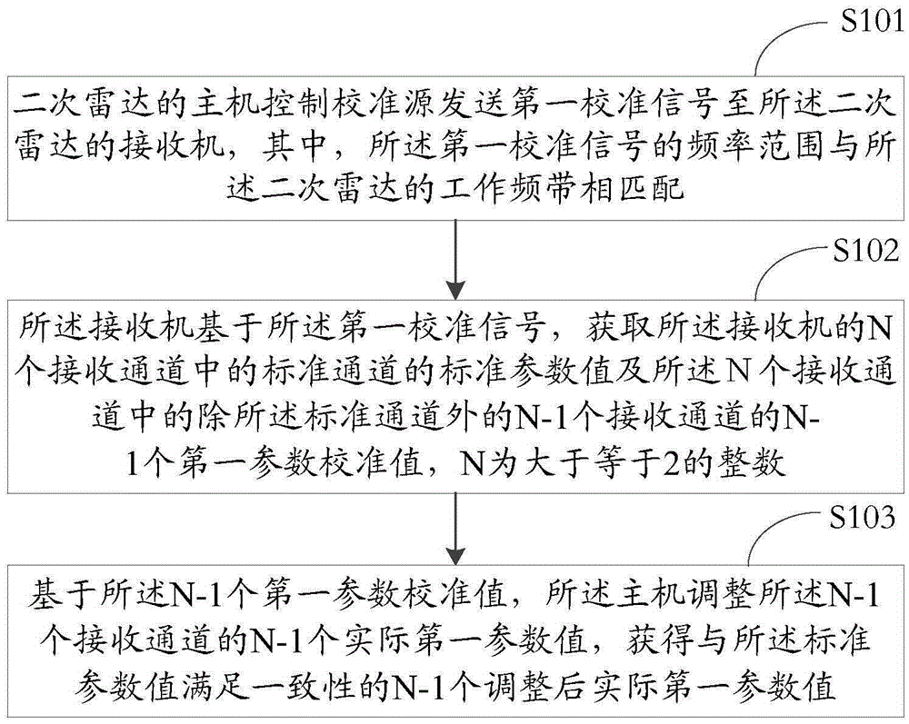
[0110] Please refer to figure 1 , a method for real-time calibration of a radio frequency channel provided in Embodiment 1 of the present application, including:

[0111] S101: The host computer of the secondary radar controls the calibration source to send a first calibration signal to the receiver of the secondary radar, wherein the frequency range of the first calibration signal matches the working frequency band of the secondary radar;

[0112] S102: Based on the first calibration signal, the receiver acquires standard parameter values ​​of standard channels among the N receiving channels of the receiver and N- N-1 first parameter calibration values ​​of one receiving channel, N is an integer greater than or equal to 2;

[0113] S103: Based on the N-1 first parameter calibration values, the host adjusts the N-1 actual first parameter values ​​of the N-1 receiving channels to obtain N that is consistent with the standard parameter value. -1 adjusted actual first parameter...

Embodiment 2

[0166] Based on the same inventive concept as Embodiment 1 of this application, please refer to Figure 9 , Embodiment 2 of the present application provides a secondary radar, including:

[0167] The antenna feed system 10 includes an antenna, a calibration source and a feeder transmission channel, the calibration source is arranged in the antenna, and the antenna is connected to the receiver through the feeder transmission channel;

[0168] The receiver 20 includes N receiving channels, the N receiving channels are connected to the feeder transmission channel, and N is an integer greater than or equal to 2;

[0169] host 30;

[0170] Wherein, when the secondary radar is performing real-time calibration, the host 30 controls the calibration source to send a first calibration signal to the receiver 20, and the frequency range of the first calibration signal matches the working frequency band of the secondary radar , based on the first calibration signal, the receiver 20 acqui...


PUM


Abstract

The invention discloses a radio frequency channel real-time calibration method and a secondary radar. The method comprises the steps that the main unit of the secondary radar controls a calibration source to transmit a first calibration signal to a receiver of the secondary radar, wherein the frequency range of the first calibration signal is matched with the working band of the secondary radar; the receiver obtains a standard parameter value of a standard channel of N receiving channels and (N-1) first parameter values of (N-1) receiving channels, except the standard channel, of the receiver based on the first calibration signal, wherein N is an integer which is greater than or equal to 2; the main unit adjusts the (N-1) actual first parameter values of the (N-1) receiving channels based on the (N-1) first parameter values, and obtains (N-1) adjusted actual first parameter values which are consistent with the standard parameter value.

Description

technical field [0001] The invention relates to the field of electronic technology, in particular to a real-time calibration method of a radio frequency channel and a secondary radar. Background technique [0002] With the continuous development of science and technology, radar technology has also been greatly improved. With the continuous combination of computer technology and radar technology, modern radar systems have gradually become fully automated, and primary and secondary radars have emerged as the times require. [0003] Among the technical indicators of the radar system, the angle measurement accuracy is a relatively key indicator, and the accuracy of its accuracy measurement directly affects the performance of the entire radar system, and an important factor affecting the angle measurement accuracy of the radar system is the radar system. Changes in magnitude and phase of the receive channel. Especially for radar systems working in a wide frequency band, it is di...

Claims


Application Information

Patent Timeline
Patent Type & Authority Applications(China)
IPC IPC(8): G01S7/40G01S13/76
CPCG01S7/40G01S13/76
Inventor 杨廷洪李宏伟熊朝廷蒋耀伟
Owner SICHUAN JIUZHOU ELECTRIC GROUP
Why Eureka
Try Eureka