
Real-time wireless step-by-step uploading type seismograph acquisition system

A collection system and seismograph technology, applied in the field of geophysical surveying, can solve the problems of poor communication link quality between the collection station and the central node, the inability to monitor the quality of the collected data in real time, and not being called a wireless seismograph, etc., to improve Efficiency, reducing the number of equipment and human resources, and improving real-time and channel-leading capabilities

Inactive Publication Date: 2016-03-23
HEFEI GUOWEI ELECTRONICS
View PDF7 Cites 2 Cited by
  • Summary
  • Abstract
  • Description
  • Claims
  • Application Information

AI Technical Summary

Problems solved by technology

However, the wireless part of most wireless seismographs is only a simple link designed to connect geographically insurmountable obstacles, which is far from being called a wireless seismograph.
There is also a wireless seismograph, in fact, each collection station collects independently, and the data is merged together after the collection is completed. This kind of seismograph cannot monitor the quality of the collected data in real time at all.
Although the WGD-1 multifunctional wireless seismograph developed by the Wuhan Institute of Engineering Science and Technology in China is a wireless seismograph in the true sense, its major problem is that the distribution range is quite limited (ordinary antennas can only support up to 150 meters) , which means that in the case of a trace spacing of 5 meters, the sum of the left and right sides of a single survey line can only support a maximum of 60 traces, and the quality of the communication link between the remote collection station and the central node is very poor

Method used


Image

  • Real-time wireless step-by-step uploading type seismograph acquisition system
  • Real-time wireless step-by-step uploading type seismograph acquisition system
  • Real-time wireless step-by-step uploading type seismograph acquisition system

Examples


Embodiment Construction

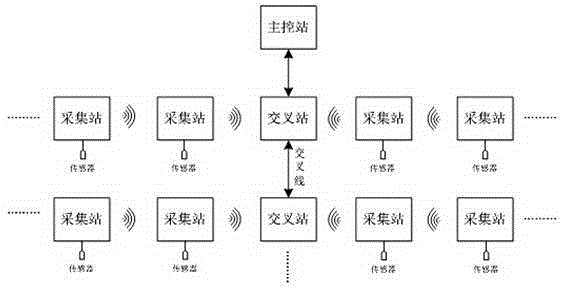
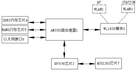
[0021] See figure 1 , a real-time wireless step-by-step seismograph acquisition system, including a plurality of acquisition stations connected to both sides of each intersection station, and adjacent acquisition stations are connected via WIFI wirelessly; see figure 2 , each collection station includes AM3352 microprocessor 1, EP3C40 chip 2 connected with AM3352 microprocessor, WL1835 module 3, DDR3 memory chip 4, NAND flash memory chip 5 and Ethernet interface 6, and EP3C40 chip 2 connected ADS1263 chip 7; WL1835 chip 3 are abstracted into two Ethernet interfaces WLAN1 and WLAN0 in the Linux operating system, wherein WLAN1 is used as a wireless access point-AP to complete the monitoring function and receive the data transmitted by the lower-level collection station. WLAN0, as the wireless sending point-Station, completes the sending function, and is responsible for combining the data collected by the current collection station and the data sent by the lower collection stati...


PUM


Abstract

The invention discloses a real-time wireless step-by-step uploading type seismograph acquisition system. The system comprises multiple acquisition stations connected at two sides of each intersection station, wherein adjacent acquisition stations are in wireless connection through WIFI, each acquisition station comprises a central processor, and a field programmable gate array, a WIFI on-chip system and a memory chip which are connected with the central processor, and an analog-to-digital converter connected with the field programmable gate array, two Ethernet interfaces WLAN1 and WLAN0 are abstracted by the WIFI on-chip system from an Linux operation system, data transmitted by a lower-level acquisition station is received by the Ethernet interfaces WLAN1, and data acquired by a present-level acquisition station and the data sent by the lower-level acquisition station are merged and are sent to an upper-level acquisition station through the Ethernet interfaces WLAN0. According to the system, the wireless step-by-step transmission technology is employed, mounting is simple, cost is low, and an acquisition transmission distance supports one line and at least one hundred channels.

Description

technical field [0001] The invention relates to the field of geophysical surveying, in particular to a real-time wireless step-by-step upload seismograph acquisition system. Background technique [0002] The most commonly used instrument in the field of geophysical exploration is the seismograph. Because the seismograph can detect geological stratification, it is widely used in oil and gas field exploration, engineering exploration and monitoring. The seismograph mainly includes an acquisition system composed of a master control station, a cross station and multiple acquisition stations, but the acquisition systems of seismographs currently on the market are almost all connected by long cables, and these copper cables are very heavy and bulky , Carrying and laying during field construction is time-consuming and laborious, which is very inconvenient. [0003] Wireless seismographs are a better substitute in this situation. However, the wireless part of most wireless seismog...

Claims


Application Information

Patent Timeline
Patent Type & Authority Applications(China)
IPC IPC(8): G01V1/00G01V1/24
CPCG01V1/003G01V1/242
Inventor 杨阳曹桂平陈静
Owner HEFEI GUOWEI ELECTRONICS
Learn More