DC-DC converter with line loss compensation function
A DC-DC, line loss compensation technology, applied in the field of circuits, can solve the problems of inability to change the compensation range, lack of flexibility, increase cost and design difficulty, and achieve the effect of good linear relationship and convenient adjustment.
- Summary
- Abstract
- Description
- Claims
- Application Information
AI Technical Summary
Problems solved by technology
Method used
Image

Examples
Embodiment Construction
[0026] In order to describe the technical content of the present invention more clearly, further description will be given below in conjunction with specific embodiments.
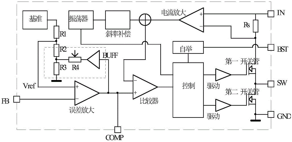
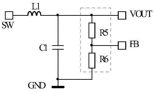
[0027] see Figure 2 to Figure 6 As shown, the structure of the DC-DC converter with line loss compensation described in the present invention is as follows figure 2 , its main structure is similar to the current mainstream current control mode DC-DC converter, except for various protection modules, the control circuit is mainly composed of a reference module, an error amplifier, a comparator, a control module, a first switch tube, and a second switch tube It is composed of the first driver stage, the second driver stage, a bootstrap module, a current amplifier, an oscillator and a slope compensation module, and the SW terminal of the control circuit and the filter circuit (see image 3 , wherein the inductance L1 and the capacitor C1 play a filtering role, and the function is to filter the switching wave...
PUM
 Abstract
Description
Claims
Application Information
 - Generate Ideas
- Intellectual Property
- Life Sciences
- Materials
- Tech Scout
- Unparalleled Data Quality
- Higher Quality Content
- 60% Fewer Hallucinations
Browse by: Latest US Patents, China's latest patents, Technical Efficacy Thesaurus, Application Domain, Technology Topic, Popular Technical Reports.
© 2025 PatSnap. All rights reserved.Legal|Privacy policy|Modern Slavery Act Transparency Statement|Sitemap|About US| Contact US: help@patsnap.com