
Portable modularized walking aid exoskeleton

An exoskeleton and modular technology, which is applied in the direction of equipment to help people walk, physical therapy, etc., can solve the problems of large exoskeleton of the lower limbs, cannot be worn independently, and poor comfort, so as to improve space utilization, improve physiological and Psychological comfort, the effect of improving stability

Active Publication Date: 2016-03-30
HARBIN INST OF TECH
View PDF5 Cites 13 Cited by
  • Summary
  • Abstract
  • Description
  • Claims
  • Application Information

AI Technical Summary

Problems solved by technology

[0003] The present invention provides a portable modular walking exoskeleton to solve the problems of large volume, heavy weight, poor comfort and inability to be worn independently in existing lower limb exoskeletons used for helping the elderly and the disabled

Method used


Image

  • Portable modularized walking aid exoskeleton
  • Portable modularized walking aid exoskeleton
  • Portable modularized walking aid exoskeleton

Examples


specific Embodiment approach 1

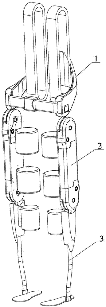
[0026] Specific implementation mode one: combine Figure 1 to Figure 11 Describe this embodiment, this embodiment includes a back module 1, two thigh modules 2 and two calf modules 3;

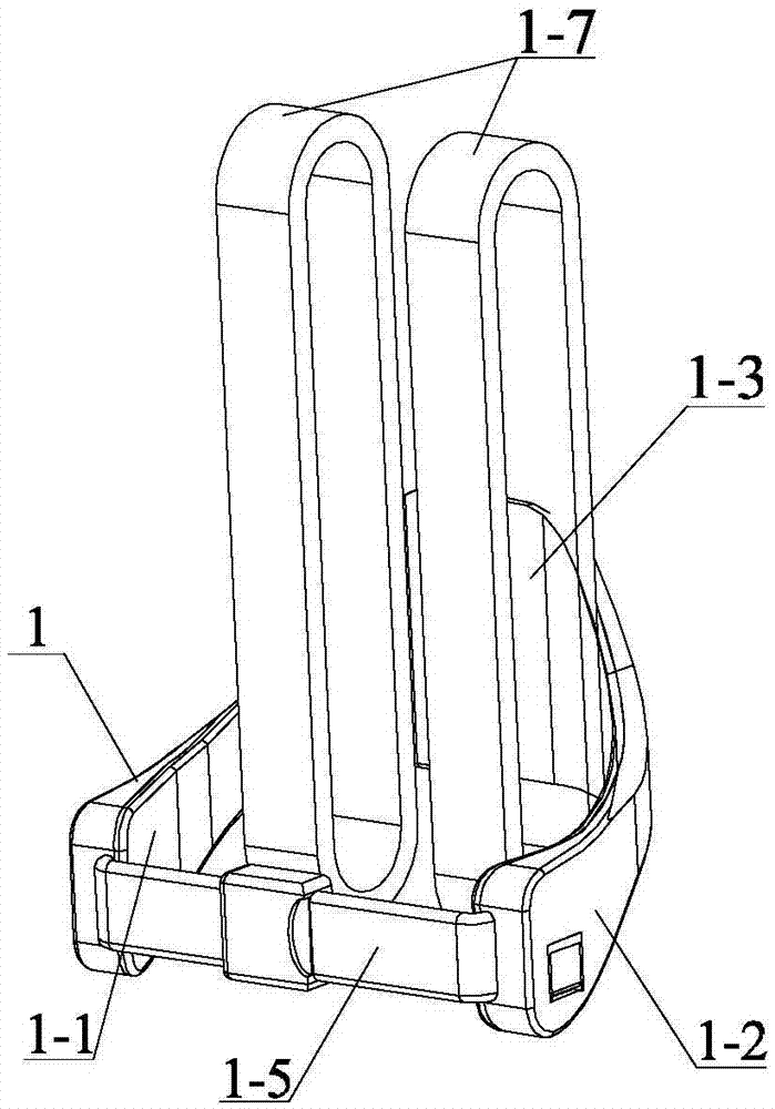
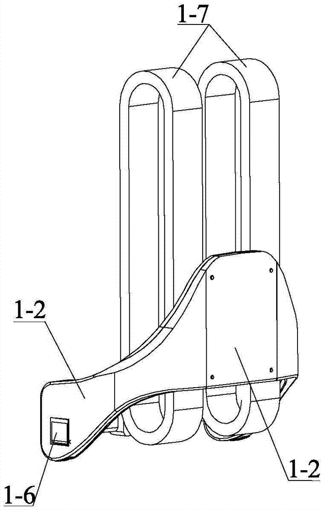
[0027] The back module 1 includes an inner back shell 1-3, an outer back shell 1-4, two inner panels 1-1, two outer panels 1-2, a waist belt 1-5, and two upper plug-in locks 1 -6 and two shoulder straps 1-7, the back inner shell 1-3 and the lower back outer shell 1-4 are arranged parallel to the front and rear, and the two inner plates 1-1 are symmetrically arranged on both sides of the lower back inner shell 1-3 , the two outer plates 1-2 are symmetrically arranged on both sides of the outer back shell 1-4, the inner back shell 1-3, the outer back shell 1-4, two inner plates 1-1 and two outer plates 1-2 forms a hollow cavity for internal routing and electrical installation, the waist belt 1-5 is arranged on the front end of the inner board 1-1, and the two ends of the waist belt 1-5 are respe...

specific Embodiment approach 2

[0032] Specific implementation mode two: combination figure 2 and image 3 Describe this embodiment, the shoulder belt 1-7 and waist belt 1-5 of this embodiment all adopt flexible material. This material is convenient for bundling. Other components and connections are the same as those in the first embodiment.

specific Embodiment approach 3

[0033] Specific implementation mode three: combination Figure 8 To illustrate this embodiment, the output member 2-5-11 of this embodiment is composed of an inverted U-shaped shift fork 2-5-11-1 and an output rod 2-5-11-2, and the inverted U-shaped shift fork 2-5- The lower end of the inverted U-shaped wall of 11-1 is provided with a mounting groove 2-5-11-3, and the output rod 2-5-11-2 is arranged on the top of the inverted U-shaped shift fork 2-5-11-1, and the output rod 2 -5-11-2 is opposite to one side of the inverted U-shaped wall of the inverted U-shaped shift fork 2-5-11-1, and the inverted U-shaped shift fork 2-5-11-1 is connected to the output rod 2-5-11- 2 made into one. Other compositions and connections are the same as those in Embodiment 1 or 2.


PUM


Abstract

The invention discloses a portable modularized walking aid exoskeleton, and relates to a lower limb exoskeleton which aims at solving the problems that an existing lower limb exoskeleton used for assisting handicapped and elderly people is large in size and weight, poor in comfort degree and not capable of being worn independently. The portable modularized walking aid exoskeleton comprises a lumbar spinal cord module, two thigh modules and two shank modules, the thigh modules are arranged under the lumbar spinal cord module in the mode of mutually serving as mirror images, the shank modules are arranged under the thigh modules in the mode of mutually serving as the mirror images, and thigh binding bands and shank binding bands are both located on the inner sides; an upper output part is connected with an upper plugging lock catch, and a lower output part is connected with a lower plugging lock catch. The portable modularized walking aid exoskeleton is used for handicapped and elderly people assistance, medical rehabilitation and the like.

Description

technical field [0001] The invention relates to a lower limb exoskeleton, in particular to a portable modular walking aid exoskeleton. Background technique [0002] For the millions of patients with loss of lower limb function due to stroke, spinal cord injury, etc. in the current society, as well as the growing elderly population, wearable lower limb exoskeletons have great expectations due to their good anthropomorphic and human-computer interaction characteristics. Application requirements are becoming more and more urgent. At present, most of the existing lower limb power-assisted exoskeletons for the purpose of helping the elderly and the disabled are bloated and heavy, complicated to put on and take off, and need to rely on auxiliary personnel. The comfort and wearing experience are poor, so they are still in the prototype test stage, and it is difficult to truly popularize and apply them. . The relatively lightweight lower extremity exoskeleton is mostly in the form...

Claims


Application Information

Patent Timeline
Patent Type & Authority Applications(China)
IPC IPC(8): A61H3/00
CPCA61H3/00A61H2201/0107A61H2201/0157A61H2201/164A61H2201/165A61H2205/10
Inventor 朱延河郑天骄袁博文赵杰
Owner HARBIN INST OF TECH
Learn More