Manufacturing method of welding jig and target assembly

A technology for welding fixtures and manufacturing methods, which is applied in welding equipment, auxiliary welding equipment, welding/cutting auxiliary equipment, etc., and can solve the problems of long-term stable production and use of ceramic targets, poor welding bonding rate of target components, and concentricity Low-level problems, to achieve the effect of improving the welding combination rate, improving concentricity, and increasing alignment

Active Publication Date: 2018-08-10
KONFOONG MATERIALS INTERNATIONAL CO LTD
View PDF6 Cites 0 Cited by
  • Summary
  • Abstract
  • Description
  • Claims
  • Application Information

AI Technical Summary

Problems solved by technology

However, in the prior art, it is difficult to weld the ceramic target and the back plate to form a ceramic target assembly
Even if the ceramic target and the back plate are welded to form a target assembly, the welding bonding rate of the target assembly is poor and the concentricity is low
It cannot meet the needs of long-term stable production and use of ceramic targets

Method used


Image

  • Manufacturing method of welding jig and target assembly
  • Manufacturing method of welding jig and target assembly
  • Manufacturing method of welding jig and target assembly

Examples


Embodiment 1

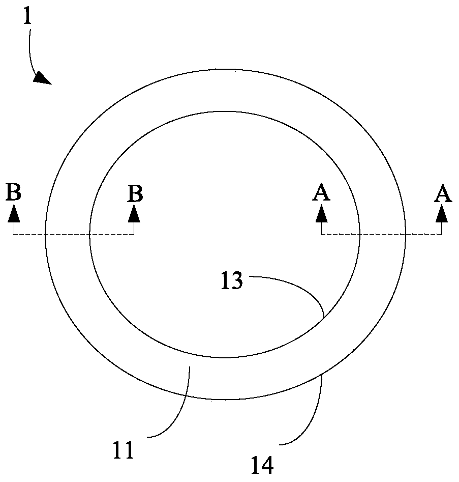
[0051] The present invention provides a welding jig 1 for welding a target and a back plate. The specific structure is as follows:

[0052] The first annular surface 11, the second annular surface 12 opposite to the first annular surface 11, the inner annular side 13 connected with the first annular surface 11 and the second annular surface 12, and the first annular surface 11 and the second annular surface 12 connected outer ring sides 14,

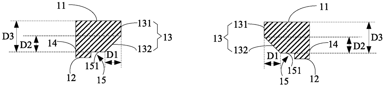
[0053] The inner ring side surface 13 includes a first inner ring side surface 131, and the first inner ring side surface 131 is connected to the first annular surface 11;

[0054] The second annular surface 12 has a groove 15, the bottom surface 151 of the groove is annular, and the opening size of the bottom surface 151 of the groove is larger than the size enclosed by the first inner ring side surface 131;

[0055]The inner ring side 13 also includes the second inner ring side 132, the groove bottom 151 and the first inner ring side ...

Embodiment 2

[0077] The present invention provides a method for manufacturing a target assembly, in which the jig of Embodiment 1 is applied in the manufacturing process of the target assembly. details as follows:

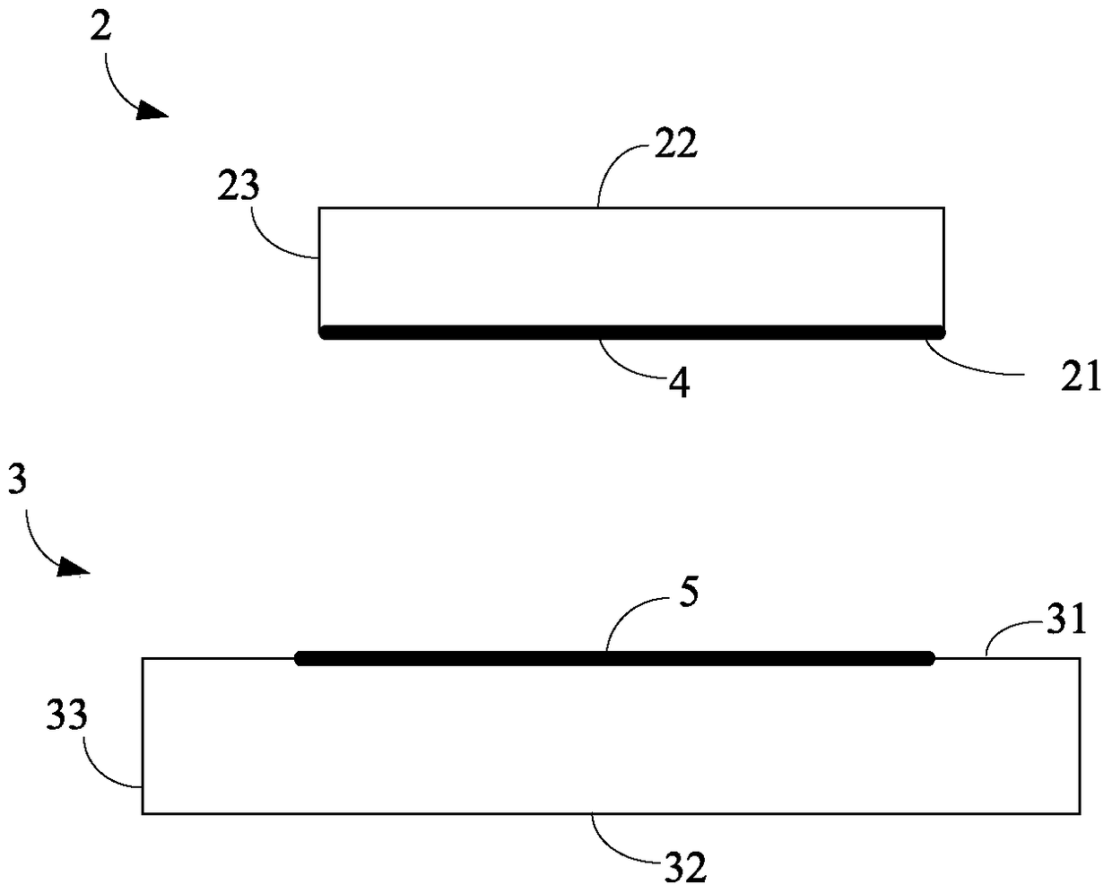
[0078] refer to image 3 , step S11 is executed to provide the target 2 , the back plate 3 and the welding jig 1 described in the first embodiment.

[0079] In this embodiment, the target material 2 is an ultra-high-purity and dense ceramic target material. Among them, the purity is at least 99.9%, and the density is at least 99%. According to the actual requirements of the application environment and sputtering equipment, the shape of the target 2 can be a cylinder, a cuboid, or a cube, and the cross-section can be a column of any one of a ring, a triangle, or other similar shapes (including regular shapes and irregular shapes). body.

[0080] refer to image 3 , in this embodiment, the target is a cylinder. The target 2 includes a target upper surface 22 , a target lowe...


PUM


Abstract

The invention discloses a welding jig and a manufacturing method for a target assembly. The manufacturing method for the target assembly includes the steps that a target, a back plate and the welding jig are provided; a first solder layer is formed on a face to be welded of the target through solder; a second solder layer is formed on a face to be welded of the back plate through solder; the target with the first solder layer and the back plate with the second solder layer are fixed to the welding jig; and the first solder layer and the second solder layer are combined through a welding process, so that the target assembly is formed. According to the target assembly formed by the manufacturing method for the target assembly, the requirements for stably producing and using the ceramic target for a long time can be met, and the service life of the target assembly can be greatly prolonged.

Description

technical field [0001] The invention relates to the field of manufacturing semiconductor sputtering targets, in particular to a manufacturing method of a welding fixture and a target component. Background technique [0002] In the semiconductor industry, the target assembly is composed of a target that meets the sputtering performance and a back plate that can be combined with the target and has a certain strength. The back plate can play a supporting role when the target assembly is assembled to the sputtering base, and has the effect of conducting heat. [0003] During the sputtering process, the working environment of the target assembly is relatively harsh. The ambient temperature of the target assembly is relatively high, for example, 300°C to 600°C; in addition, one side of the target assembly is cooled by cooling water, while the other side is at 10°C. -9 In the high vacuum environment of Pa, a huge pressure difference is formed on the opposite sides of the target a...

Claims


Application Information

Patent Timeline
Patent Type & Authority Patents(China)
IPC IPC(8): B23K3/08B23K37/04
Inventor 姚力军潘杰相原俊夫大岩一彦王学泽王科
Owner KONFOONG MATERIALS INTERNATIONAL CO LTD
Why Eureka
Try Eureka