Automobile auxiliary power system and new energy automobile

A power system and vehicle auxiliary technology, which is applied in the field of vehicle engineering, can solve problems such as high cost and scattered structure, and achieve the effects of simplifying structure, improving compactness, and improving work efficiency

Inactive Publication Date: 2016-03-30
胡挺
View PDF9 Cites 2 Cited by
  • Summary
  • Abstract
  • Description
  • Claims
  • Application Information

AI Technical Summary

Problems solved by technology

[0003] In new energy vehicles, the engine and drive motor provide the driving force of the vehicle, and the accessory system is provided with a separate power source. The accessory system is driven by the corresponding motor, which is costly and has a scattered structure.

Method used


Image

  • Automobile auxiliary power system and new energy automobile

Examples


no. 1 example

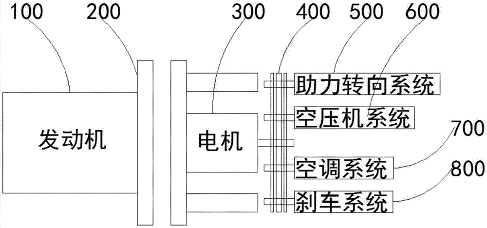
[0036] For the first embodiment, refer to figure 1 The vehicle auxiliary power system includes an engine 100 , a motor 300 and a vehicle accessory system, the engine 100 and the motor 300 are connected through a clutch, and the motor 300 and the vehicle accessory system are connected through a power coupling 400 .

[0037] Wherein, the engine 100 is a prior art machine that can convert other forms of energy into mechanical energy; the motor 300 is a prior art machine that can convert mechanical energy into electrical energy and convert electrical energy A machine that converts mechanical energy; the automobile accessory system is a prior art, referring to other systems on the automobile except the system that provides driving power for the automobile; the clutch is an existing technology, which is used to separate or engage the input Shaft and output shaft to realize power cutting or transmission; the power coupler 400 is also an existing technology, which generally refers to ...

no. 2 example

[0057] The second embodiment, the device provided by the embodiment of the present invention, its implementation principle and technical effect are the same as the first embodiment, for brief description, for the parts not mentioned in the device embodiment, please refer to the corresponding content.

[0058] In this embodiment, the clutch is a hydraulic clutch.

[0059] Wherein, the hydraulic clutch is the prior art, and it adopts fluid (generally oil) as transmission medium, and its structure usually comprises an input shaft, has a speed-up gear train; The driven wheel and an impeller shell are composed; an output shaft has a driven wheel, and the driven wheel and the impeller can be operatively combined; generally, the impeller shell and the impeller are made of materials with small specific gravity and large stress bearing range to reduce centrifugal stress.

[0060] The purpose of using the hydraulic clutch is that it has the function of absorbing the vibration and impa...

no. 3 example

[0061] The third embodiment, the implementation principle and technical effect of the device provided by the embodiment of the present invention are the same as those of the first embodiment. For a brief description, for the parts not mentioned in the device embodiment, please refer to the corresponding content.

[0062] In this embodiment, the clutch is an electromagnetic clutch.

[0063] Wherein, the electromagnetic clutch controls the engagement and disengagement of the clutch by turning on and off the power of the coil, and the working mode includes power-on combination and power-off combination.

[0064] The purpose of using the electromagnetic clutch is that it has the characteristics of high-speed response, high durability, and easy maintenance.


PUM


Abstract

The invention provides an automobile auxiliary power system and a new energy automobile and belongs to the field of vehicle engineering. The automobile auxiliary power system comprises an engine, a motor and an automobile accessory system, wherein the engine is connected with the motor through a clutch, and the motor is connected with the automobile accessory system through a power coupler. The new energy automobile comprises the automobile auxiliary power system. The automobile auxiliary power system and the new energy automobile provide power for the automobile accessory system in an engine and motor matched mode, the engine or the motor can be selected as a power source, the structure of the accessory system is simplified, the compactness of the accessory system is improved, and the working efficiency of the automobile auxiliary power system and the accessory system is improved. The auxiliary power system has a power generation function, can charge an automobile power battery and effectively overcomes the defects in the prior art.

Description

technical field [0001] The invention relates to the field of vehicle engineering, in particular, to an auxiliary power system of an automobile and a new energy automobile. Background technique [0002] Traditional automobiles use the internal combustion engine as the power source of the vehicle, and the internal combustion engine is also the power source of other accessory systems of the vehicle, including power steering system, air compressor system, air conditioning system, brake system, and generator system. [0003] In new energy vehicles, the engine and drive motor provide the driving force of the vehicle, and the accessory system is provided with a separate power source. The accessory system is driven by the corresponding motor, which is costly and has a decentralized structure. Contents of the invention [0004] The object of the present invention is to provide a vehicle auxiliary power system and a new energy vehicle to improve the above problems. [0005] The pre...

Claims


Application Information

Patent Timeline
Patent Type & Authority Applications(China)
IPC IPC(8): B60K25/06
CPCB60K25/06
Inventor 胡挺
Owner 胡挺
Why Eureka
Try Eureka