Novel bridge for melting snow through waste heat of power plant and construction method

A thermal melting and bridge technology, used in bridges, bridge parts, bridge construction, etc., can solve problems such as traffic congestion, prone to traffic accidents, and impassable vehicles, to ensure roads, save the cost of artificial snow removal, and reduce snow. good effect

Inactive Publication Date: 2016-03-30
HEILONGJIANG COLLEGE OF CONSTR
View PDF6 Cites 5 Cited by
  • Summary
  • Abstract
  • Description
  • Claims
  • Application Information

AI Technical Summary

Problems solved by technology

[0002] The weather in the north is relatively cold, and it snows more often. Although there are artificial or mechanical snow removal, it can only be done after the snow stops, especially the bridges have a certain slope, so get off at the edge of the snow. Walking on the side will form a mirror road, vehicles will not be able to pass, causing serious traffic jams, and it is very prone to traffic accidents

Method used


Image

  • Novel bridge for melting snow through waste heat of power plant and construction method
  • Novel bridge for melting snow through waste heat of power plant and construction method

Examples


Embodiment 1

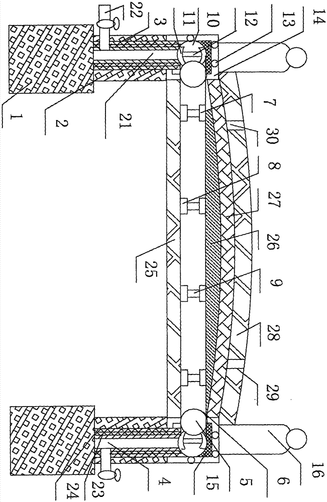
[0024] A new type of bridge that melts ice and snow using waste heat from a power plant. Its composition includes: a bridge pile foundation 1, the bridge pile foundation is connected to a bridge pier 2, and a group of vertical through holes 3 are opened on the bridge pier. The main heat delivery pipe 4 is inserted into the through hole, and the main heat delivery pipe is connected to the horizontal branch heat transfer pipe 5. The horizontal branch heat transfer pipe is provided with a group of connection holes 6, and the connection holes are connected to a group of cross-branched heat transfer pipes. The top of the heat release tube is connected to the upper arc-shaped connecting plate 7, the bottom of the inside of the heat release tube is connected to the lower arc-shaped connecting plate 8, and the upper arc-shaped connecting plate is connected to the The lower arc-shaped connecting plates are supported and connected by 1-5 pillars 9, and the heat release pipes are laid in ...

Embodiment 2

[0026] In the new bridge that melts ice and snow using waste heat from a power plant described in Example 1, the main heat transfer pipe is connected to the transverse branch heat transfer pipe through an elbow 10, and the part of the elbow that is arranged horizontally Both the top and the bottom of the interior are connected to arc-shaped connecting plates 11, and support columns 12 are connected between the arc-shaped connecting plates. Because the elbow is supported by arc-shaped connecting plates and supporting columns, it is safe to use and will not be crushed to ensure smooth air intake.

Embodiment 3

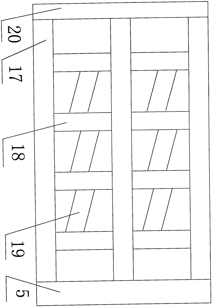
[0028] In the novel bridge using waste heat from a power plant to melt ice and snow described in Example 1, the transverse branch heat transfer tubes are installed in a steel frame, and the steel frame includes a group of square brackets 13, and between the square brackets The steel bar frame is connected to the concrete 15 through the horizontal steel bar 14, and the steel bar frame and the concrete are both connected to the side bridge guardrail 16.


PUM


Abstract

The invention discloses a novel bridge for melting snow through waste heat of a power plant and a construction method. The novel bridge for melting snow through waste heat of the power plant comprises bridge pile foundations connected with piers; a set of vertical through hole is formed in each pier; a main heat sending pipe is inserted into each vertical through hole and connected with a transverse branch heat transferring pipe; each transverse branch heat transferring pipe is provided with a set of connection hole; the connection holes are connected with a set of crossed heat release pipes; the tops inside the heat release pipes are connected with upper arc connection boards; the bottoms inside the heat release pipes are connected with lower arc connection boards; the upper arc connection boards and the lower arc connection boards are supported and connected through one to five supporting columns; the heat release pipes are laid in a bridge face. The novel bridge is used for melting the snow.

Description

Technical field: [0001] The invention relates to a novel bridge and a construction method for melting ice and snow by utilizing waste heat of a power plant. Background technique: [0002] The weather in the north is relatively cold, and it snows more often. Although there are artificial or mechanical snow removal, it can only be done after the snow stops, especially the bridges have a certain slope, so get off at the edge of the snow. Walking while walking forms a mirror road, and vehicles cannot pass, causing serious traffic jams, and traffic accidents are very prone to occur. Invention content: [0003] The purpose of the present invention is to provide a new type of bridge and a construction method that can ensure that there will be no ice surface on the bridge surface in snowy days and that vehicles can be unblocked by using waste heat from power plants to melt ice and snow. [0004] Above-mentioned purpose realizes by following technical scheme: [0005] A new type ...

Claims


Application Information

Patent Timeline
Patent Type & Authority Applications(China)
IPC IPC(8): E01D19/00E01D19/06E01C11/26
CPCE01C11/26E01D19/00E01D19/06
Inventor 孙宇于晓冬
Owner HEILONGJIANG COLLEGE OF CONSTR
Why Eureka
Try Eureka