Tidal current energy generating device fixed to water bottom

A technology of power generation device and tidal current energy, applied in ocean energy power generation, engine components, machines/engines, etc., can solve problems such as high difficulty, reduced impeller speed, and inability to commercialize horizontal axis hydro-generators, reducing maintenance and installation costs, enabling assembly and replacement, overcoming non-commercialization effects

Active Publication Date: 2016-03-30
HANGZHOU LINDONG NEW ENERGY TECH INC +1
View PDF7 Cites 2 Cited by
  • Summary
  • Abstract
  • Description
  • Claims
  • Application Information

AI Technical Summary

Problems solved by technology

However, the maintenance and replacement of traditional tidal current power generation devices are also carried out in the sea, which is difficult and costly
Even, the entire tidal current energy generation device is scrapped due to the damage of some components. This is one of the important reasons for the high cost of the tidal current energy generation device, and it is also the direct reason why the existing tidal current energy generation device cannot be operated on a large scale and commercially. reason
[0006] Horizontal axis hydro-generators in particular are more difficult and costly to repair since all their equipment, including the impeller and generator, is submerged
Therefore, even though the power generation efficiency of the horizontal-axis hydro-generator is higher than that of the vertical-axis hydro-generator, the horizontal-axis hydro-generator still cannot be commercialized
However, at present, technicians in the field of ocean energy generation have ignored the improvement of maintenance methods
[0007] In addition, traditional tidal current power generation devices generally only use one

Method used


Image

  • Tidal current energy generating device fixed to water bottom
  • Tidal current energy generating device fixed to water bottom
  • Tidal current energy generating device fixed to water bottom

Examples


Embodiment Construction

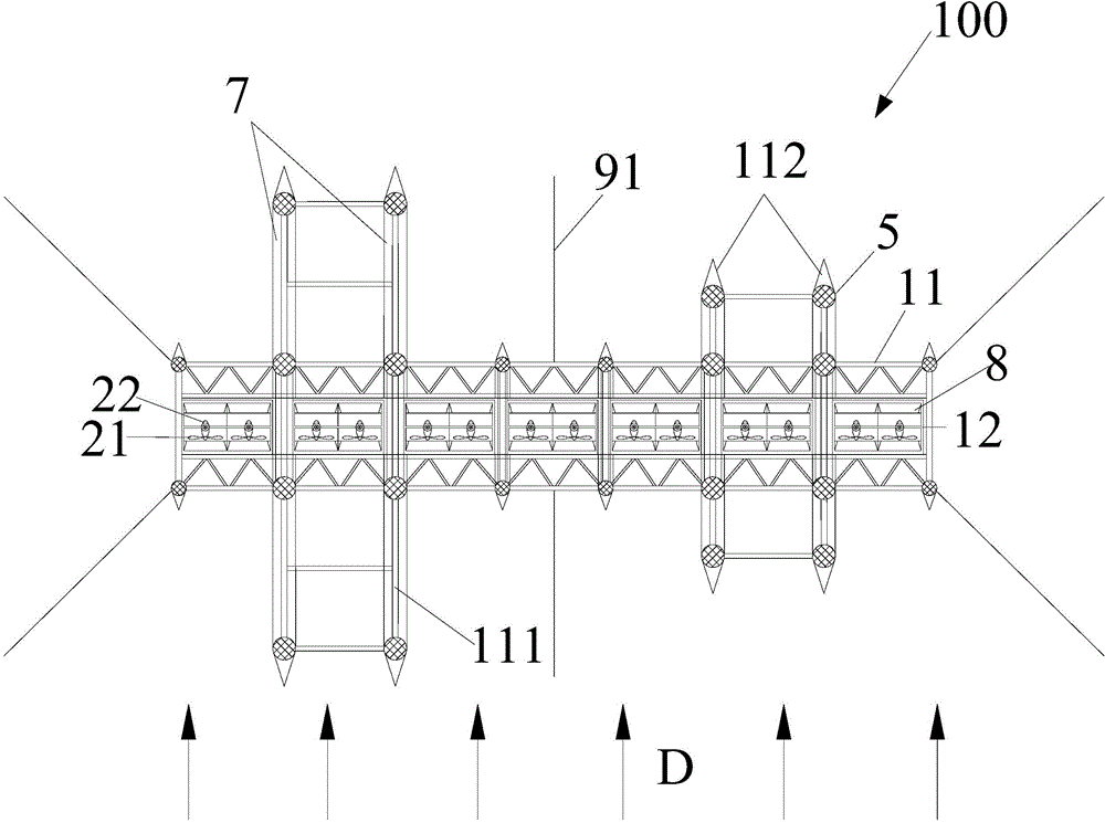
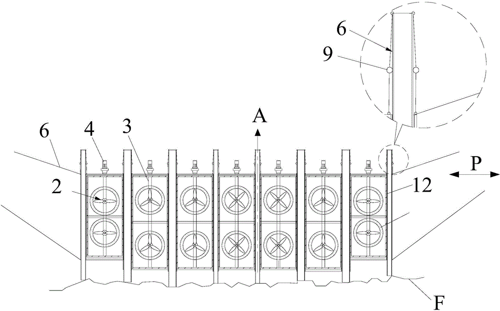
[0031] figure 1 Shown is a top view of the tidal current energy generating device fixed on the bottom of the water according to the first embodiment of the present invention. figure 2 Shown is a front view of the tidal current energy generating device fixed on the bottom of the water according to the first embodiment of the present invention when no pile is driven. image 3 Shown is a schematic diagram of the fence in the tidal current energy generation device fixed on the bottom of the water according to the first embodiment of the present invention. Figure 4 Shown is a schematic diagram of a part of the outer frame and the outer sleeve provided according to the first embodiment of the present invention. Figure 5 Shown is a schematic diagram of the piling process for fixing the tidal current energy generating device to the bottom of the water according to the first embodiment of the present invention. Please also refer to Figure 1 to Figure 5 .

[0032] In the first e...


PUM


Abstract

The invention provides a tidal current energy generating device fixed to water bottom. The tidal current energy generating device comprises an outer framework, at least three inner frameworks, at least three horizontal shaft water wheel generators, at least three rotary shafts, multiple outer sleeve pipes and multiple inner sleeve pipes. The at least three inner frameworks are separably arranged in the outer framework. The at least three horizontal shaft water wheel generators are arranged into the at least three inner frameworks.At least one horizontal shaft water wheel generator is correspondingly arranged on each rotary shaft. At least one rotary shaft is correspondingly installed on each inner framework. At least three driving units are connected with the rotary shafts in order to drive the rotary shafts to rotate. The multiple outer sleeve pipes are fixed onto the outer framework. A part of each inner sleeve pipe is connected to the bottom end and the water bottom of a corresponding outer sleeve pipe.

Description

technical field [0001] The invention belongs to the field of ocean energy power generation, in particular to a tidal current energy power generation device fixed on the bottom of the water. Background technique [0002] There are two fixing methods for the tidal current energy generation device. One is to fix and suspend in the water through structures such as steel cables and buoys, and the other is to fix to the bottom of the water by piling. Since the two fixing methods are to fix the generating device at different positions in the water, the construction methods are completely different, and the structures of the corresponding tidal current energy generating devices are also quite different. [0003] The existing construction method for fixing the tidal current energy generating device on the bottom of the water is mainly to fix it by blasting and ramming the prefabricated concrete piles at the bottom of the water by construction workers. However, in order to ensure the...

Claims


Application Information

Patent Timeline
IPC IPC(8): F03B13/26
CPCY02E10/30
Inventor 林东陈历姜芳
Owner HANGZHOU LINDONG NEW ENERGY TECH INC
Why Eureka
Try Eureka