
Damping type valveless hydraulic synchronous servo system

A hydraulic synchronization and servo system technology, applied in the direction of servo motors, fluid pressure actuators, mechanical equipment, etc., can solve the problems of low synchronization accuracy, complex oil circuits, leakage pollution, etc., achieve the effect of improving accuracy and solving difficult maintenance

Active Publication Date: 2016-03-30
南通大学技术转移中心有限公司
View PDF6 Cites 1 Cited by
  • Summary
  • Abstract
  • Description
  • Claims
  • Application Information

AI Technical Summary

Problems solved by technology

But this kind of oil circuit is only suitable for occasions where the change of external load is small or the requirements for the movement speed of the mechanism are not high
It can be seen that the traditional synchronization system has low synchronization accuracy, complex oil circuit, and leakage pollution.

Method used


Image

  • Damping type valveless hydraulic synchronous servo system
  • Damping type valveless hydraulic synchronous servo system
  • Damping type valveless hydraulic synchronous servo system

Examples


Embodiment 1

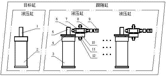
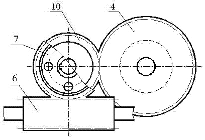
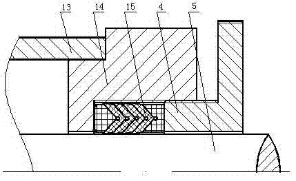
[0027] A damping valveless hydraulic synchronous servo system, which uses a valveless system composed of a servo motor and a variable pump to drive multiple hydraulic cylinders on the valveless hydraulic parallel synchronous circuit, and sensors are used on each parallel branch to monitor the speed, pressure and The displacement is used for data collection, and the controller compares and analyzes the data; in each parallel branch, the hydraulic cylinder on the first branch is the target cylinder, and the hydraulic cylinders on the other branches are follower cylinders, and friction is added to the cylinder heads of the follower cylinders The resistance device adjusts the movement speed of the output end of each cylinder through the friction resistance device to realize the synchronization of displacement, speed and pressure.

[0028] The frictional resistance device includes a gear pressing block mechanism and a V-shaped sealing ring. The gear pressing block is connected to th...

Embodiment 2

[0040] A damping valveless hydraulic synchronous servo system, which uses a valveless system composed of a servo motor and a variable pump to drive multiple hydraulic cylinders on the valveless hydraulic parallel synchronous circuit, and sensors are used on each parallel branch to monitor the speed, pressure and The displacement is used for data collection, and the controller compares and analyzes the data; in each parallel branch, the hydraulic cylinder on the first branch is the target cylinder, and the hydraulic cylinders on the other branches are follower cylinders, and friction is added to the cylinder heads of the follower cylinders The resistance device adjusts the movement speed of the output end of each cylinder through the friction resistance device to realize the synchronization of displacement, speed and pressure. There are four parallel circuits.

[0041] The frictional resistance device includes a gear pressing block mechanism and a V-shaped sealing ring. The gea...


PUM


Abstract

The invention discloses a damping type valveless hydraulic synchronous servo system, wherein a valveless system formed by combination of a servo motor and a variable pump is adopted to drive multiple hydraulic cylinders on a valveless hydraulic parallel synchronous loop, a sensor is adopted for each parallel branch to carry out data collection on speed, pressure and displacement, and a controller is used for carrying out contrastive analysis on data; in each parallel branch, a hydraulic cylinder on a first branch is a target cylinder, hydraulic cylinders on the rest branches are follow-up cylinders, frictional resistance devices are additionally arranged at the covers of the follow-up cylinders, and the movement speed of the output end of each cylinder is adjusted by the frictional resistance devices, so as to realize synchronization of displacement, speed and pressure. The system disclosed by the invention is environment-friendly and energy-saving, simple to operate and high in control precision.

Description

technical field [0001] The invention relates to a damping valveless hydraulic synchronous servo system. Background technique [0002] The hydraulic synchronous control system is not a single system, it contains many comprehensive disciplines, and is an important research field in the mechatronic-electrical-hydraulic integration technology, not only in theory, but also in actual industrial production. widely. However, due to production conditions and other factors, the processing accuracy requirements of the components used in the hydraulic synchronous control system are difficult to meet the strict conditions, and their performance cannot meet the requirements. [0003] In order to achieve the effect of synchronization, the movement of each cylinder should not interfere with each other, and its movement speed should not change with the change of the external load. Traditional series synchronous hydraulic system: the working pressure of the pump is equal to the sum of the l...

Claims


Application Information

Patent Timeline
IPC IPC(8): F15B11/22
CPCF15B11/22
Inventor 曹阳吴国庆钟超超茅靖峰周井玲张旭东邱锴文
Owner 南通大学技术转移中心有限公司
Learn More